
Mated and free dimensions of mechanical connections. Recommendations for choosing fits of matching sizes
The dimensions of parts of assembly units are divided into coupled and free. Mating dimensions are the dimensions of mating parts (connected), the nominal dimensions of which must be the same. They ensure the specified position of parts in the assembly unit,
the accuracy of its operation, proper assembly and disassembly conditions, the required interchangeability of parts. After the parts are manufactured, these dimensions must be checked by inspectors.
Free dimensions usually refer to the surfaces of parts that do not come into contact with other parts of the assembly unit and do not significantly affect the operation of the mechanism. However, the individual values of the free dimensions of adjacent parts can be interrelated by certain design conditions. These sizes are called free.
dependent.
Correct application of such independent free dimensions on the drawing of a part is a necessary condition for ensuring the correct operation of the product and its installation.
In Fig. 88 shows valve seat 1, pressed into body 2 along diameter d 1, the values of which for the seat and body are conjugate dimensions. The diameters d 2 of the seat and d 3 of the body are free dependent dimensions, since there are no high requirements for manufacturing accuracy; it is only necessary that d 2 saddles< d 3 корпуса/ Здесь же вободными зависимыми размерами являются размеры l 1 седла и l 2 отверстия в корпусе,для них тоже необходима условие l 1 >l 1
Lecture No. 8 Rules for executing assembly drawings
Rules for the execution of assembly drawings (AS) and drawings common types(VO) is determined by GOST 2.109-68. In accordance with this standard, the assembly drawing must contain (Fig. 89):
a) an image of an assembly unit giving an idea O the location and mutual connection of the components connected according to this drawing and providing the ability to assemble and control the assembly unit; the product on the assembly drawing must be shown in its working position;
b) instructions on the nature of the interface and methods for its implementation, as well as instructions on the method of making permanent connections (welded, soldered, etc.);
c) position numbers of the components included in the product;
d) main characteristics of the product;
developments that must be performed or controlled according to this assembly drawing;
f) overall dimensions of the product;
g) installation and connection dimensions, as well as the necessary reference dimensions.
It is allowed to depict on the assembly drawing:
a) moving parts of the product in extreme or intermediate positions with appropriate dimensions;
b) border (adjacent) products (“furnishings”) and dimensions that determine their relative position.
Assembly drawings may be made SIMPLIFIED.
It is allowed not to show on assembly drawings
a) Chamfers, roundings, grooves, recesses, protrusions, knurls, notches, braids and other small elements;
b) gaps between the rod and the hole:
c) covers, shields, casings, partitions, etc., if it is necessary to show the component parts of the product covered by them. An appropriate inscription is made above the image: “Cover item 3 is not shown”;
d) inscriptions on plates, branded strips, scales;
e) products made from transparent material are depicted as opaque;
f) the springs are not shown completely, 2-3 turns from each end: products located behind the coil spring. depicted only by sections of turns. depicted up to the zone that conventionally covers these products and is defined by the axial lines of the sections of the turns;
g) it is allowed to depict one of several identical holes, grooves and other elements if they are evenly spaced; for all others, only their location is indicated: the sections show the component parts of the products uncut. for which independent assembly drawings have been prepared;
h) a welded, soldered, glued and similar product made of a homogeneous material assembled with other products in sections and sections is hatched as a monolithic body (in one direction), depicting the boundaries between the parts of the welded product with solid main lines.
In longitudinal sections they are shown unshaded:
a) standard fasteners (bolts, screws, studs, nuts, washers, pins, dowels, balls, etc.);
b) non-hollow shafts;
c) stiffeners, flywheel spokes. teeth of gears and worms.
In cases where the assembly drawing of the product can be made in A4 format, it can be combined with the specification, as shown in Fig. 86.
In the assembly drawing, all components of the assembly unit are numbered in accordance with the item numbers specified in the specification of this assembly unit. Position numbers are indicated on the shelves of leader lines drawn from the images of the component parts in those images. on which the corresponding constituent parts are projected as visible, as a rule. on the main views and sections replacing them.
Position numbers are placed parallel to the main inscription of the drawing outside the outline of the image and grouped in a column or line, if possible on the same line. The font size of item numbers should be one to two sizes larger than the font size adopted for dimensional numbers on the same drawing.
Price 3 kopecks.
STATE STANDARD
USSR UNION
OPTICAL BENCH TRAPEZOIDAL PROFILE
MAIN AND MATING DIMENSIONS. TECHNICAL REQUIREMENTS
GOST 12995-82
Official publication
USSR STATE COMMITTEE ON STANDARDS
UDC 681.7,072.6: 006.354 Group P41
STATE STANDARD OF THE USSR UNION
OPTICAL TRAPEZOIDAL BENCH
Main and associated dimensions. Technical requirements
Optical bench of trapezoidal profile Mam and conjugated dimensions technical requirements
GOST 12995-67
By Decree of the USSR State Committee on Standards dated July 29, 1982 No. 2948, the introduction date was established
Failure to comply with the standard is punishable by law
This standard applies to an optical bench of a trapezoidal profile with dovetail guides, intended for the installation of optical instruments, spectral devices, individual parts and devices and their movements parallel to the optical and sighting axes, and establishes the main and mating dimensions of the rail and riders.
1. MAIN AND MATING DIMENSIONS
1 1. The main dimensions of the optical bench are: the length and height of the rail, the length of the rater base and the distance from the edge of the base to the center of the rater column (Fig. 1-3).
1.2. The associated dimensions of the optical bench are: the width of the rail guide and the dovetail angle (Fig. 2), the angle at the support surface of the rater and the mounting diameter of the rater column (Figure 3)
1.3 The main and mating dimensions of the rail must correspond to those indicated in the drawing. 2, the raters - to hell. 3.
Official publication Reproduction prohibited
Reissue. July 1987
© Standards Publishing House, 1988
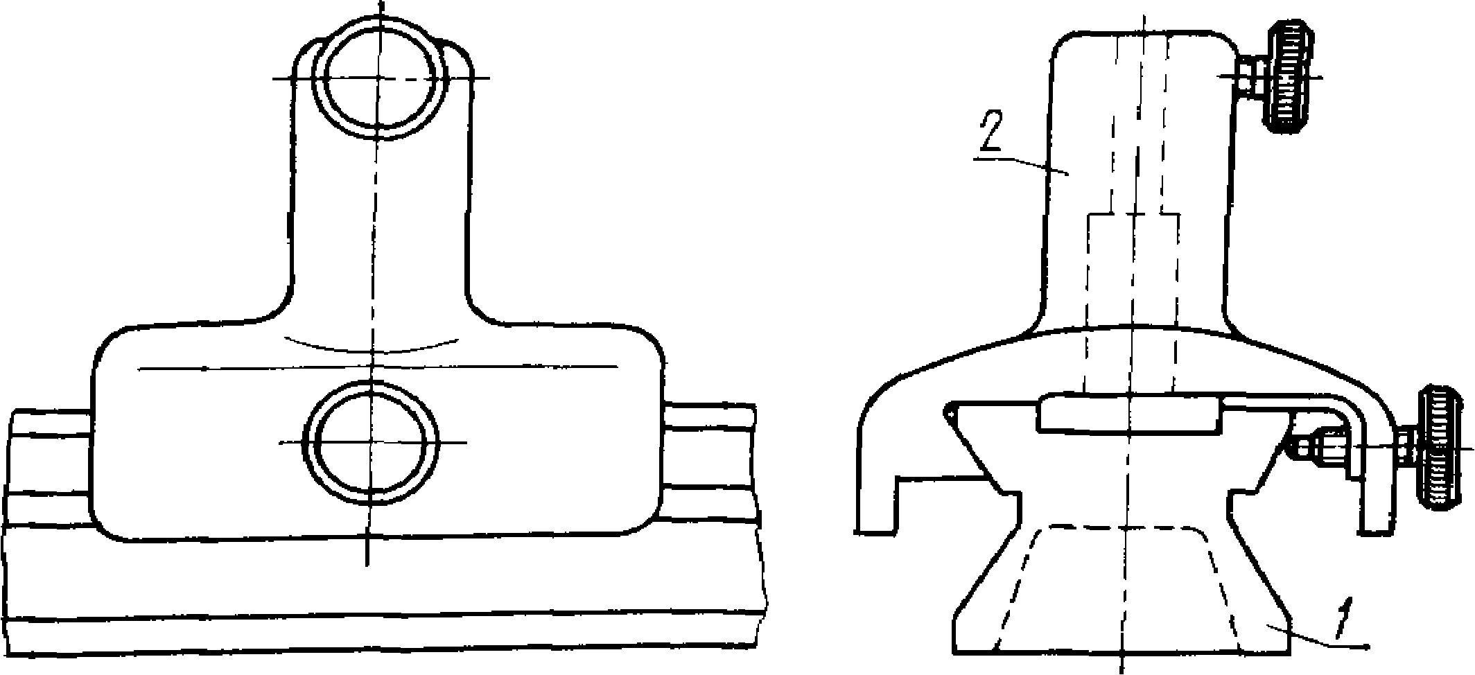
/-rail; 2-rater Damn. 1
A~A
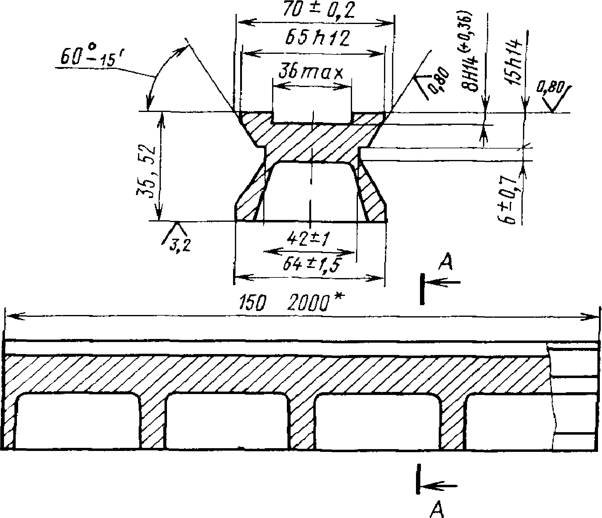
* The size is prescribed in the range from 150 to 500 mm in 50 mm intervals, in the range from 500 to 2000 mm in 250 mm intervals. Unspecified maximum deviations of dimensions: holes according to NI, shafts - according to
Н4, the rest - by ±
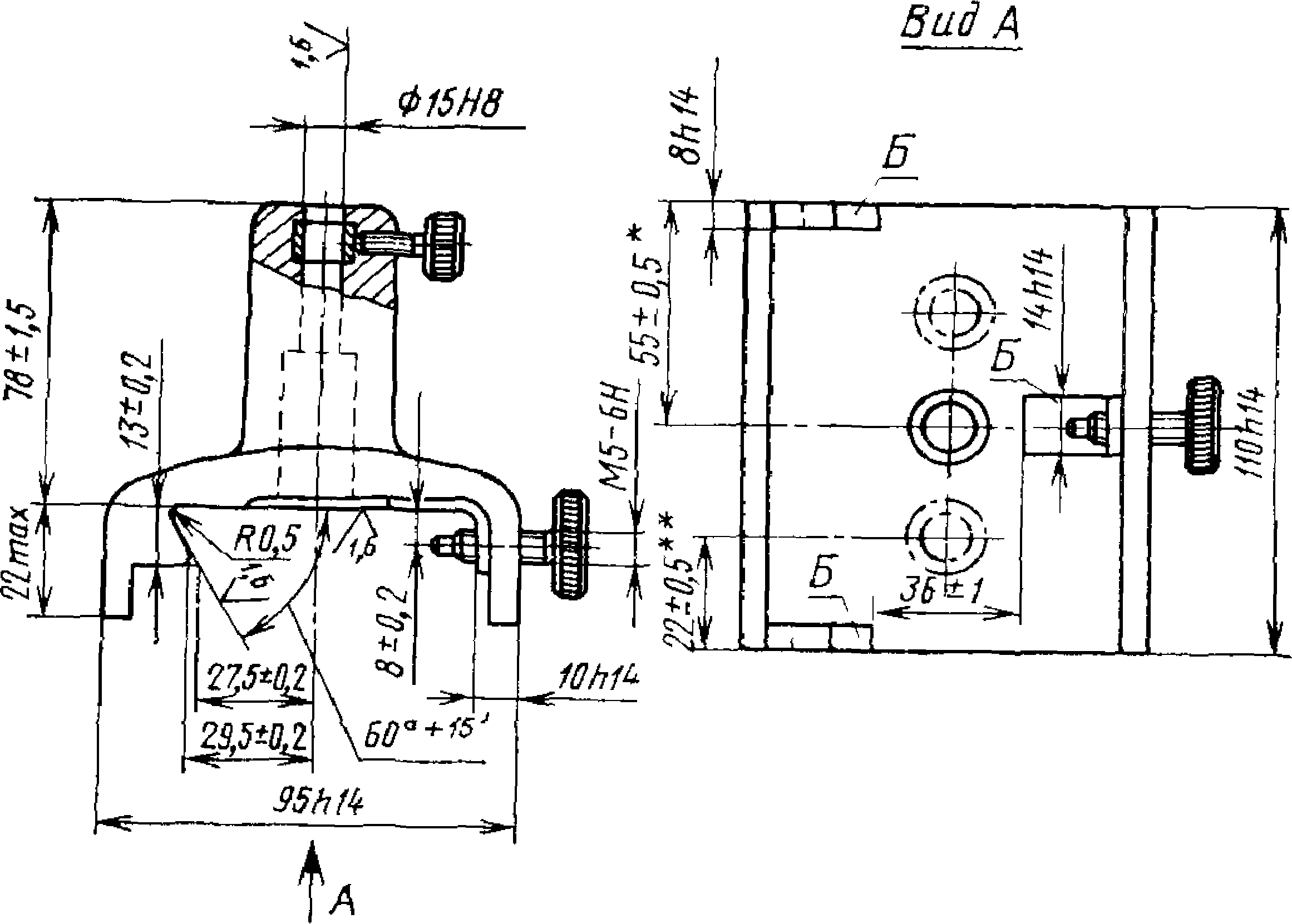
* Size refers to the symmetrical placement of the rater column relative to the edges of the base.
** Size refers to the asymmetrical position of the rater column relative to the edges of the base.
Notes:
1. Damn. 1-3 do not define the design.
2. It is allowed, by agreement between the consumer and the manufacturer, to produce raters with columns, bases and supporting surfaces of other sizes.
2. TECHNICAL REQUIREMENTS
2.1. Optical benches with a trapezoidal profile should be manufactured in accordance with the requirements of this standard according to working drawings approved in the prescribed manner.
2.2. During the manufacturing process, the internal stresses of the rail must be removed.
2.3. The flatness tolerance of the mating surfaces of the rail and the riders in two directions (along the length of the guides and along the width) must correspond to the degree of accuracy 10 according to GOST 24643-81.
2.4. The straightness tolerance of the rail guides in the horizontal plane along the length must correspond to accuracy degree 12 according to GOST 24643-81.
2.5. The flatness tolerance of the three bearing surfaces B of the rater relative to the common adjacent plane is 0.1 mm.
2.6. The tolerance for perpendicularity of the column axis relative to the three supporting surfaces B of the rater must correspond to accuracy degree 8 according to GOST 24643-81.
2.7. Depending on the location of the column relative to the edges of the base, the raters are made symmetrical or asymmetrical.
Editor V. M. Lysenkina Technical editor E. V. Mityai Proofreader G. I. Chuiko
Delivered to aab. 10/12/87 Go to the oven. 01/26/88 0.5 el. p.l. 0.5 el. cr.-ott. 0.19 academic publication l.
Circulation 3000 Price 3 kopecks.
Order "Badge of Honor" Publishing house of standards, 123840, Moscow, GSP,
Novopresnensky lane, 3.
Vilnius Printing House Standards Publishing House, st. Mindaugo, 12/14. Zach. 4370.
|
Magnitude | |||
|
Name |
Designation |
||
|
international/folk | |||
|
0 S N 0 V N S | |||
|
kilogram | |||
|
Electric current strength | |||
|
Thermodynamic temperature | |||
|
Quantity of substance | |||
|
The power of light | |||
|
EXTRA EJ |
1Init SI |
||
|
Flat angle | |||
|
Solid angle |
steradian | ||
DERIVATIVE SI UNITS WITH SPECIAL NAMES
|
Expression through basic and pre- |
||||
|
Magnitude |
U I U Li in and p in K- |
Designation |
||
|
PaNMagain* |
SI complete units |
|||
|
Pressure |
M" 1 - KGS" 2 |
|||
|
m 2 * KG-s -2 |
||||
|
Power |
m 2 * KG-S" 3 |
|||
|
Amount of electricity | ||||
|
Electrical voltage |
M/kg-s" 3 A~* |
|||
|
Electrical capacity |
m“ 2 kg - 1 s 4 *A a |
|||
|
Electrical resistance |
m^kg-s -3 A |
|||
|
Electrical conductivity |
m -2 -kg“, -s e *A a |
|||
|
Magnetic induction flux |
m 2 * kg - s~ 2 A“ 1 |
|||
|
Magnetic induction |
kg s- 2 A- 1 |
|||
|
And inductance |
m 2 *kg s -2 - A“ 2 |
|||
|
Light flow | ||||
|
Illumination |
M- 2 ■ cd sr |
|||
|
Radionuclide activity |
becquerel | |||
|
Absorbed dose ionizes | ||||
|
total radiation Equivalent radiation dose | ||||
Machines consist of parts, assemblies and assemblies that are connected in a certain order and with established accuracy. Accuracy is one of the most important indicators of the quality of machine parts, significantly influencing all criteria for the performance and reliability of mechanisms, and, consequently, the output performance of machines.
Machine parts cannot be manufactured absolutely accurately and always have some deviations from the nominal dimensions. Therefore, the interchangeability of parts is of great importance for the operation, manufacture and design of machines.
Interchangeability and standardization. Interchangeability as a principle for the design and production of parts was proposed and implemented for the first time in late XIX V. in the production of rifles. It ensures correct assembly and replacement during repair of independently manufactured parts and assemblies without additional processing, in compliance with quality and cost-effectiveness requirements.
Interchangeability- this is the ability of independently manufactured parts and assemblies to take their places in the machine without additional processing and ensure high-quality operation. Interchangeability allows for: independent processing of parts using high-performance methods (since the need to fit one mating part to another is eliminated); effective application flow and conveyor assembly; processing with standard tools; high-performance simple and reliable control of products using gauges; quick replacement of failed machine parts with pre-manufactured spare parts; acceleration of design, etc.
The interchangeability of parts and assemblies can be complete or incomplete (partial). In the latter case, the correct connection of parts and assemblies is ensured only for part of them, manufactured with proper accuracy. Another part of the parts, manufactured less accurately, is assembled by selection, using compensators and various technological means.
Full interchangeability is ensured by the standard system tolerances and landings .
Standardization. Standardization is of great importance in mechanical engineering. Standardization is ensuring the uniformity and quality of products by introducing special, mandatory regulatory documents - standards.
Standardization of parts, components and assemblies of machines covers - general standards, classification and terminology and methods.
To ensure the interchangeability of parts, assemblies and complexes and streamline their production on the scale of an enterprise or a group of countries, there are standards: enterprises - STP, industries - OST, state - GOST, CMEA - ST CMEA, international - MS. Their compliance is mandatory at all stages of production, marketing and operation of products.
The basis for standardization is sizes, quantitatively assessing the geometric parameters of parts.
Size - the numerical value of a linear quantity (diameter, length, etc.) in the selected units of measurement. The dimensions indicated on the drawings of parts or connections are called nominal.
They are obtained from calculations (for strength, stiffness, etc.) or taken for design reasons. To typify technological processes, limit the number of tools, standard sizes of parts, the accepted nominal dimensions are rounded to the values according to GOST 6636-89 “Normal linear dimensions”.
The standard provides four rows of sizes in descending order of preference P5, P10, P20 and P40, each of which represents a geometric progression with a denominator corresponding to;  ;
;  And
And  .
.
When manufacturing parts, the actual size, i.e. the size established by measurement with an acceptable error, may coincide with nominal size only by chance, since technological errors (inaccuracies in the manufacture of tools, equipment, etc.) of a systematic and random nature cause inevitable processing errors and dispersion of part sizes.
It has been established that to ensure correct assembly (geometric interchangeability) and normal operation, parts may have some dispersion of sizes relative to the nominal values.
The maximum and minimum dimensions between which the actual size of a part can lie are called maximum dimensions.
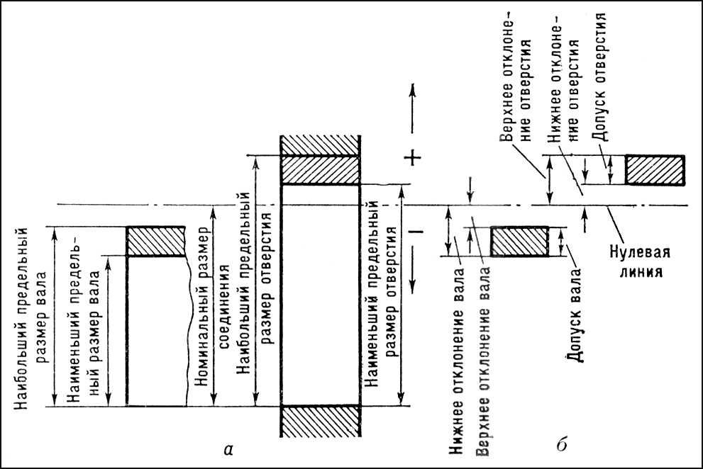
Rice. 52. Limit dimensions holes and shaft defining tolerance fields.
In Fig. 52 schematically shows cylindrical shafts (a) and holes (b) aligned along a generatrix with nominal maximum diameters. Let us denote them by Dmax And Dmin- for the hole and d max And dmin- for the shaft.
The algebraic difference between the measured size (actual and limit, etc.) and the corresponding nominal value is called deviation.
Actual deviation- algebraic difference between real and nominal sizes; maximum deviation - algebraic difference between the maximum and nominal sizes.
GOST 25346-82 uses the following symbols for deviations: upper and lower deviations: (initial letters of the French words Ecart - deviation, Superieur - upper, Inferieur - lower)
for hole
ES = Dmax-d EI = Dmin-d;
es= d max - d; ei = dmin-d,
Where d- nominal diameter.
The deviation values can be positive and negative. When shown schematically (see Fig. 46), they are set relative to the nominal dimensions, which serve as the starting point (positive deviations are laid upward, and negative deviations are laid down from the zero line). For mating (contact) surfaces of parts, the nominal size can be common (for example, for coaxial mating of the shaft and hub).
Economically feasible deviations in the dimensions of parts are determined Unified admission system and landings established by STSEV 144-75.
Size tolerance is the difference between the largest and smallest permissible maximum sizes. Tolerance is designated by the letter T and is always positive. (Fig. 52).
Size tolerance is indicated by letters IT, e.g. shaft size tolerance
IT=T d = d max - d min = es - ei,
and hole size tolerance
IT= T D =D max - D mln = ES-EI.
Tolerance field T D - the field limited by the upper and lower deviations is determined by the numerical value of the tolerance and its position relative to the nominal size.
The following main deviations are provided (in the size range of 1...500 mm) in the order of decreasing the gap and increasing the interference in the corresponding fits (lowercase letters of the Latin alphabet - for shafts, uppercase letters - for holes):
a in c d e f g h j s k
A B C D E F G H J s K
m n p r s t u ν x y z
Μ Ν Ρ R S Τ U V Χ Υ Z
In a graphical representation, the tolerance field is enclosed between two lines corresponding to the upper and lower deviations relative to the zero line (Fig. 52). The location of the tolerance field relative to the zero line is usually denoted by one or two letters of the Latin alphabet - uppercase for holes and lowercase for shafts (for example, Н5, F7, h8, j s 8 etc.). With the same tolerance, the part bigger size more difficult to manufacture than a smaller part. The numerical values of the tolerances in the main size range of 1...500 mm are taken to be proportional to the cubic root of the part size with a small correction proportional to the size.
Therefore, the tolerance size IT prescribed depending on the diameter,
entering the tolerance unit
Here d- in mm, and IT = ai.
Dependence (10.2) represents a cubic parabola, and i is a measure of accuracy, since the tolerance is obtained by multiplying i by the dimensionless coefficient a:
For the most common size range in mechanical engineering from 1 to 500 mm, for which formula (1) is valid, the standardization of numerical tolerance values was carried out by establishing 13 main standard size intervals.
Exact adherence to dependence (10.2) for all sizes in the range from 1 to 500 mm is impractical, since for sizes close to each other there is no point in changing the tolerances. Therefore, when compiling standardized numerical values of tolerances in the range 1...500 mm, 13 values of tolerance units were selected, equal to the ordinates of the average geometric values of the intervals: up to 3, 3-6, 6-10, 10-18, 18-30, 30-50.50 - 80, 80-120, 120-180, 180-250, 250 - 315, 315 - 400, 400 - 500. In other words, for each interval a constant value i (and therefore tolerance T) is accepted, equal to the ordinate of the geometric mean value of the interval D means when calculating the tolerance unit using formula (10.2), the cube root is taken not from any given number, but from the geometric mean value of the size interval in which the size was located. For example, a strength calculation when designing a part (assembly) of a product gave a result of 12 mm. Since the size of 12 mm is in the interval 10-18 mm, then the geometric mean value of the interval ![]() . This means that for a diameter of 12 mm D = 13.4 mm (average geometric size) The breakdown of the range is 1-500 mm. into 13 intervals is carried out in such a way that the values of i, calculated using formula (10.2) based on the extreme values of the interval, do not differ in value by more than 5 - 8%.
. This means that for a diameter of 12 mm D = 13.4 mm (average geometric size) The breakdown of the range is 1-500 mm. into 13 intervals is carried out in such a way that the values of i, calculated using formula (10.2) based on the extreme values of the interval, do not differ in value by more than 5 - 8%.
Relationship between tolerance and tolerance unit
| Tolerance designation | Tolerance value | Tolerance designation | Tolerance value |
| ΙΤ5 | 7i | IT12 | 160i |
| ΙΤ6 | 10i | IT13 | 250i |
| ΙΤ7 | 16i | IT14 | 400i |
| ΙΤ8 | 25i | IT15 | 640i |
| ΙΤ9 | 40i | IT16 | 1000i |
| ΙΤ10 | 64i | IT17 | 1600i |
| ITll | 100i |
![]()
Rice. 53 . Relationship between tolerance unit i and nominal value of size D
Tolerances are set in accordance with nineteen qualifications(degrees of accuracy), designated in descending order of accuracy 0.1; 0; 1; 2; ... 17. Quality is characterized by the number of tolerance units. Quality reflects the accuracy of the technological process. In the CMEA ESDP, for sizes up to 500 mm, 19 qualifications are established: IT01, IT0, IT1, IT2, IT3,..., IT17, IT - International Tolerance (International Tolerance or ISO Tolerance). IT8, for example, means the system is approved according to the 8th ISO quality. The number of tolerance units in formula (2) is a series of geometric progression R5 with the denominator ![]() .
.
Given the existing diversity of technological processes, it turned out that the R5 series chosen for regulation is quite sufficient, on the one hand, to ensure the really necessary accuracy for parts or products to fulfill their functional purpose, on the other hand, it rationally limits the choice of values of the number of tolerance units to the number that actually necessary and economically feasible.
Qualities 4 and 5 apply:
a) for parts that determine the accuracy of the operation of highly precise machines, precision machines, dividing machines;
b) for particularly stressed parts of high-speed machines in cases where accuracy largely determines the load or stress distribution;
c) for parts of high-speed mechanisms when silent operation is necessary.
Qualifications 6...8 are considered basic in modern production.
Quality 9 is typical for parts in low-speed machines and mechanisms and other machines with reduced accuracy requirements.
Qualities 10, 11 are used for low-precision, low-speed parts, assemblies and machines; they provide for the possibility of partial use of parts made without removing chips from clean-drawn round steel and pipes, cold-formed parts, etc.
Qualities 12 and 13 are used at the most minimum requirements to the quality of processing, usually for auxiliary devices, they are oriented for production parts without removing chips.
Qualifications 14...17 are intended for the free dimensions of parts, i.e., the dimensions of non-mating surfaces, and also for the dimensions of workpieces after pre-processing. These precision grades are obtained through stamping, drawing, mold casting, rough turning, etc.
The values of the upper and lower limit deviations are indicated on the drawings in three ways:
1) in small numbers (mm) beyond the nominal size; deviations equal to zero are not entered. Deviations may have the same or different signs, for example 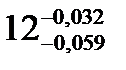 , 20 +0.018 or
  ;
;
2) symbol tolerance fields, consisting of a letter and a number indicating quality, for example 12G8, 20h10;
3) simultaneous indication of the tolerance range and digital deviation values (in parentheses), for example 12G8, 20h10 (-0.08).
Nature of pairing- the fit of two coaxial cylindrical parts (male - shaft and female - hole) depends on their actual dimensions. If the hole diameter is larger than the shaft diameter, then the connection between them will be gap(Fig. 54; positive difference in diameters), providing free axial and circumferential movement of one part relative to another. If the hole size is smaller than the shaft size (negative size difference), then a interference(Fig. 55).
Landings are selected depending on the purpose and operating conditions of equipment and mechanisms, their accuracy, and assembly conditions. In this case, it is necessary to take into account the possibility of achieving accuracy using various methods of processing the product.
Preferred plantings should be applied first. Fittings are mainly used in the hole system (the range of dimensional cutting and calibrating tools for holes is reduced). Shaft system fits are appropriate when using some standard parts (for example, rolling bearings) and in cases where a shaft of constant diameter is used along the entire length to install several parts with different fits on it.
The tolerances of the hole and shaft in the fit should not differ by more than 1 - 2 grades. A larger tolerance is usually assigned to the hole.
Clearances and interferences should be calculated for most types of connections, especially for interference fits, fluid bearings and other fits. In many cases landings can be assigned by analogy with previously designed products, similar in terms of working conditions.
Landings with clearance. Combination of hole H with shaft h ( sliding landings) are used mainly in fixed joints when frequent disassembly is necessary (replaceable parts), if it is necessary to easily move or rotate parts one relative to the other when setting or adjusting, to center fixedly fastened parts.
Transitional landings. Designed for fixed connections of parts that undergo assembly and disassembly during repairs or due to operating conditions. Mutual immobility of the parts is ensured by keys, pins, pressure screws, etc. Less tight fits are prescribed if there is a need for frequent disassembly of the joint, if disassembly is inconvenient and there is a possibility of damage to adjacent parts; tighter - if high centering accuracy is required, under shock loads and vibrations.
Preference fits. The choice of fit is made from the condition that with the least interference, the strength of the connection and transmission, loads are ensured, and with the greatest interference, the strength of the parts is ensured.
2.1.2. Selection of landings
a) mating of the shaft and spacer ring (d 1 = 65 mm):
choose a fit with a gap of H7/h6, because this fit provides a connection between parts that must move easily when tightened.
b) mating of the glass and body (d 2 = 105 mm):
We choose the transitional fit H7/js6, because this fit provides good centering without requiring significant effort for assembly and disassembly.
c) mating of the lid and glass (d 3 = 108 mm):
choose an interference fit (N max = 95 µm, N min = 25 µm).
2.2 Calculation of the mating of the shaft with the spacer ring for a fit with a gap of Æ65 H7/h6 in a hole system d 1 = 65 mm
a) for shaft Æ65h6:
es = 0 µm
ei = – 19 µm
Td = es – ei = 0 – (–19) = 19 µm
b) for spacer ring Æ65H7:
ES = + 30 µm
EI = 0 µm
TD = ES – EI = +30 – 0 = 30 µm
Limit dimensions
a) for the shaft:
d max = d + es = 65 + 0 = 65 mm
d min = d + ei = 65 – 0.019 = 64.981 mm
b) for spacer ring:
D max = D + ES = 65 + 0.030 = 65.030 mm
D min = D + EI = 65 + 0 = 65 mm
Limit clearances
S max = D max – d min = 65.030 – 64.981 = 0.049 mm = 49 µm
S min = D min – d max = 65 – 65 = 0 µm
Clearance fit tolerance
TS = S max – S min = 49 – 0 = 49 µm
Examination
N max = d max – D min = 65 – 65 = 0 µm
N min = d min – D max = 64.981 – 65.030 = – 0.049 mm = – 49 µm
TN = N max – N min = 0 – (–49) = 49 µm
TSN = TD + Td = 30 + 19 = 49 µm
Layout of tolerance fields for the shaft and spacer ring
2.3 Calculation of the interface between the cup and the body using a transitional fit Æ105 H7/js6 in a hole system d 2 = 105 mm
Limit deviations
a) for glass Æ105js6:
es = + 11 µm
ei = – 11 µm
b) for housing Æ105H7:
ES = + 35 µm
EI = 0 µm
Limit dimensions
a) for a glass:
d max = d + es = 105 + 0.011 = 105.011 mm
d min = d + ei = 105 – 0.011 =104.989 mm
b) for the body:
D max = D + ES = 105 + 0.035 = 105.035 mm
D min = D + EI = 105 + 0 = 105 mm
Mating and free dimensions of mechanical connections
The dimensions of parts of assembly units are divided into coupled and free. Mating dimensions are the dimensions of the mating (connected) parts, which must be the same. They ensure the specified position of parts in the assembly unit, the accuracy of its operation, proper conditions for assembly and disassembly, and the required interchangeability. After the parts are manufactured, these dimensions must be checked by inspectors from the quality control or quality control service.
The issues of correct measurement and application of related dimensions are given special attention when taking sketches of device parts.
Available sizes usually refers to the surfaces of parts that do not come into contact with other parts of the assembly unit and do not significantly affect the operation of the mechanism. However, the values of individual free dimensions of adjacent parts can be mutually related by certain design conditions (the values of the free dimensions of one part are applied in accordance with similar dimensions of adjacent parts). These sizes are called free dependent.
Correct application of such interdependent (dependent) free dimensions on the drawing of parts is a necessary condition for ensuring the correct operation of the product, its installation and dismantling. Therefore, when taking sketches, the free dependent dimensions of the device parts are identified and the correctness of their measurement and application on the sketches is checked.
The nature of the relationship between the dimensions of the parts of an assembly unit is determined by its design. Let's explain this with examples.
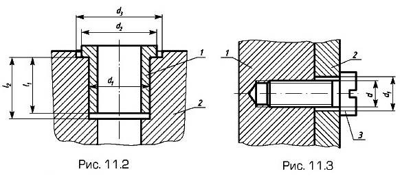
In Fig. Figure 11.2 shows valve seat 1, pressed into body 2 along diameter d 1, the value of which for the seat and body is the conjugate size. At the same time, the diameters d 2 of the seat and d 3 of the body are free dependent dimensions, since there are no great requirements for manufacturing accuracy; it is only necessary that d 3 > d 2 . Here, the free dependent dimensions are the dimensions l 1 of the seat and l 2 holes in the body; they also require the condition
Figure 11.3 shows a screw connection between two parts. The outer diameters of the thread d of screw 3 and part 1 are conjugate (the internal and middle diameters of the thread are also conjugate dimensions, but they are not indicated in the thread designation on the drawings of the parts). The outer diameter d of the screw thread and the diameter d 1 of the hole in part 2 are free dependent dimensions, since the hole in part 2 must be larger than the diameter of the screw.
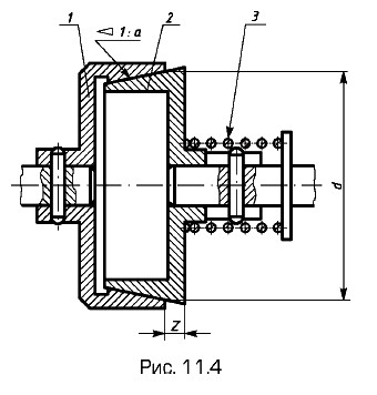
The mating dimensions of two conical surfaces with the same taper are shown using the example of a friction clutch (Fig. 11.4). The conjugation of conical surfaces is determined by the size of the conjugate dimensions - their taper 1: a and diameters d (taper is the ratio of the difference in diameters of two sections of the cone to the distance between them). In this case, the diameters d are specified in the “main” plane, which for the outer cone (left coupling half 1) is the plane of its larger base. For the internal cone (right coupling half 2), the position of the “main” plane is determined by the size l from one of the ends of the part.
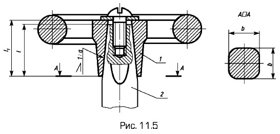
The conjugate dimensions of two pyramidal surfaces are shown in Fig. 11.5. To transmit torque from flywheel 1 to vacuum valve rod 2, their coupling is made in the form of a tetrahedral pyramid. The associated dimensions here are slope 1: a of the landing faces relative to the axis of the rod and the cross-sectional dimensions of the hole in the flywheel and the end of the rod, determined in the “main” plane, i.e. dimensions b of the side of the square (in section A - A). The length l of the rod seating surface and the length l 1 of the flywheel seating surface are free dependent dimensions with the condition l 1 > l to ensure axial tightening of the flywheel on the rod.
Other examples of axial conjugate and free dependent dimensions are given below.