
Deviations of shafts and holes. Dimensions on parts: tolerance range, accuracy standards. Actual, maximum deviation - Drawing
Designations:
· IT tolerance = International tolerance;
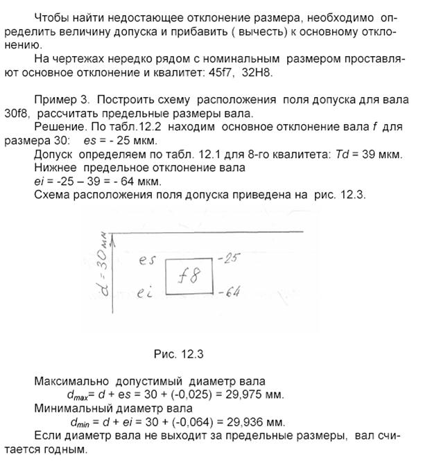
· Upper and lower deviations, ES = Ecart Superieur, EI = Ecart Interieur,
· For holes capital letters(ES, D), for shafts small (es, d).
Hole tolerance zone diagram. According to the drawing - 4 mm, maximum dimensions- 4.1-4.5. In this case, the tolerance field does not cross the zero line, since both limit sizes are higher than the nominal ones.
Basic terms and definitions GOST 25346-89.
· Shaft- a term conventionally used to designate the external elements of parts, including non-cylindrical elements.
· Hole- a term conventionally used to designate the internal elements of parts, including non-cylindrical elements.
· Main shaft- a shaft whose upper deviation is zero.
Main hole- a hole whose lower deviation is zero.
- Actual size- element size established by measurement.
- Limit dimensions- two maximum permissible sizes of an element, between which the actual size must be (or can be equal to).
- Nominal size- the size relative to which deviations are determined.
- Deviation- algebraic difference between the size (actual or maximum size) and the corresponding nominal size.
- Actual deviation- algebraic difference between the real and the corresponding nominal sizes.
- Maximum deviation- algebraic difference between the limit and the corresponding nominal sizes. There are upper and lower limit deviations.
- Upper deviation ES, es- algebraic difference between the largest limit and the corresponding nominal sizes.
Note. ES- upper deviation of the hole; es- upper shaft deflection.
- Lower deviation EI, ei- algebraic difference between the smallest limit and the corresponding nominal sizes.
Note. EI- lower deviation of the hole; ei- lower shaft deflection.
- Main deviation- one of two maximum deviations (upper or lower), which determines the position of the tolerance field relative to the zero line. In this system of tolerances and landings, the main one is the deviation closest to the zero line.
- Zero line- a line corresponding to the nominal size, from which dimensional deviations are plotted when graphically depicting tolerance and fit fields. If the zero line is located horizontally, then positive deviations are laid up from it, and negative deviations are laid down.
· Tolerance T- the difference between the largest and smallest limit sizes or the algebraic difference between the upper and lower deviations.
Note. Tolerance is an absolute value without a sign.
· IT standard approval- any of the tolerances established by this system of tolerances and landings.
· Tolerance field- a field limited by the largest and smallest maximum dimensions and determined by the tolerance value and its position relative to nominal size. In a graphical representation, the tolerance field is enclosed between two lines corresponding to the upper and lower deviations relative to the zero line.
· Quality (degree of accuracy)- a set of tolerances considered as corresponding to the same level of accuracy for all nominal sizes.
· Tolerance unit i, I- a multiplier in tolerance formulas, which is a function of the nominal size and serves to determine the numerical value of the tolerance.
Note. i- tolerance unit for nominal dimensions up to 500 mm, I- tolerance unit for nominal dimensions St. 500 mm.
Linear dimensions, angles, surface quality, material properties, specifications are indicated:
1. in the form of a numerical tolerance value;
2. in the form of two maximum deviations between which the actual size () is located;
3. combination of letters (letters) main deviation and quality numbers ();
4. in the form of the largest and smallest limit values;
5. the sign “greater than or equal to” () or “less than or equal to” ();
6. percent.
Quality is a measure of accuracy. As quality increases, accuracy decreases (tolerance increases). 
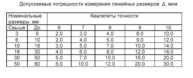
- The absolute value of the tolerance (in microns) depending on the quality and size:
Dimensional tolerance value, µm
![]()
Fit is the nature of the connection of mating parts, determined by the gap or interference, that is, the difference in their sizes before assembly in accordance with the designated tolerance.
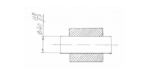
The system of tolerances and fits exists in two versions: shaft system - the main size is the size of the shaft, and the hole size is selected with different clearance or interference; hole system - the main size is the hole size, and the shaft size is specified with the required clearance or interference.
Plantings are designated by letters of the Latin alphabet: holes - in capital letters, shafts - in lowercase letters. The accuracy of the fit is determined by the quality of the tolerance.
Different fits determine the degree of freedom of relative movement of parts; they are assigned based on the operating conditions of machines and mechanisms, their accuracy and assembly conditions. Landings according to the nature of the connection of parts are divided into 3 groups:
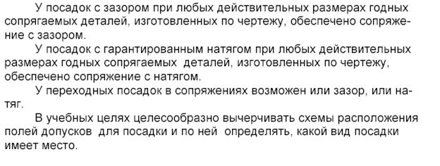
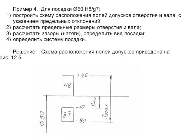
· Fit with (guaranteed) clearance - a connection with a guaranteed clearance, that is, the smallest permissible hole size is greater than or equal to the largest maximum shaft size. Designated from a to h (from A to H).
· Transitional fit - a connection with a possible gap or interference depending on the actual dimensions of the shaft and hole. Designated j to n (J to N).
· Fit with (guaranteed) interference fit - connection with guaranteed interference, that is, the largest allowable hole size is less than or equal to the smallest allowable shaft size. Designated p to z (P to Z).
Interference connection is a technological operation for obtaining a conditionally detachable connection, which is obtained by inserting one part (or part of it) into the hole of another part during an interference fit. Usually, parts with cylindrical or conical surfaces are connected; these surfaces can also be elliptical, prismatic, etc. To obtain a reliable connection, interference is required (a positive difference in the diameters of the shaft and hole). After assembly, the shaft and hole, due to elastic and plastic deformations, take on the same size. The connection with interference is assembled by pressing or temperature deformation.
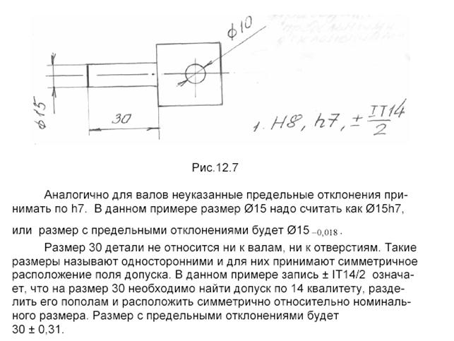
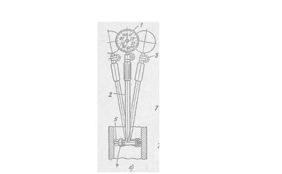
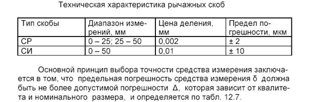
To measure shafts and holes, calipers with an error of ±0.1 mm and ±0.05 mm are used. To measure shafts, smooth micrometers are used with an error of ±4 µm. Indicator bore gauges are used to measure holes.
![]()
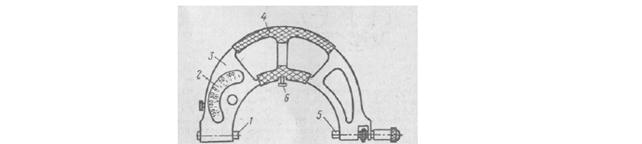
Calibers and templates are designed to measure a part according to the same size and are scale-free tools. They are especially widely used in mass and serial production to control the size, shape and relative position of surfaces. Limit calibers. Calibers for checking shafts - staples (GOST 2216-84*, 18355-73*). The through side (OL) has a size equal to the largest maximum shaft size, and the non-through side (NOT) has a size equal to the smallest maximum shaft size. Double-sided sheet staple Sheet single-sided staple from 1 to 50 mm from 1 to 180 mm Stamped double-sided staple Adjustable bracket from 3 to 100 mm from 0 to 330 mm Application of staples. The passing side of the gauges (PR) for shafts must pass through the surface of the controlled size, and the non-passing side (NOT) must not pass into it. The measuring surfaces of the gauges should be lightly lubricated. The use of excessive force during measurement leads to incorrect readings and premature wear of the measuring surfaces of the instrument. Gauges for measuring holes - plugs (GOST 14807-69*, 14827-69*). Types of plugs The flow side (OL) of the plug has a size equal to the smallest limit size of the hole, and the non-go side (NOT) has a size equal to the largest limit size of the hole. Double-sided plug with inserts with Double-sided plug with nozzles. conical shank. Measurement limits from 30 to Measurement limits from 1 to 50 mm 100 mm Single-sided cork with inserts with Double-sided sheet corks. conical shank. Measurement limits from 18 to 100 mm Measurement limits from 6 to 50 mm Application of plugs. The passing side of the plug (PR) must pass into the hole being tested, and the non-passing side (NOT) must not pass. Templates. Templates for controlling lengths and heights. Control of lengths and heights using limit templates is carried out in the same way as staples and plugs, i.e. by moving their measuring surfaces relative to the surfaces of parts (products) being checked.
Lecture 15
Tolerance – the difference between the largest and smallest limit sizes or the absolute value of the algebraic difference between the upper and lower deviations. Denoted as T.
Quality – a set of tolerances that vary depending on the nominal size. Qualities cover the tolerances of mating and non-mating parts. To standardize various levels of dimensional accuracy from 1 mm to 500 mm, 19 qualifications have been established in the UDDP (Unified System of Tolerances and Landings) system, they are designated by numbers: 01; 0; 1; 2 ... 17.
Standard tolerances (GOST 25346-89) established by ESPD are designated: IT01, IT0; IT1 ... IT17, The letters IT indicate “ISO approval” (ISO = ISO - International Standard Organization). So, record IT7 denotes ISO 7th grade approval.
The tolerance unit i (I) is set as a unit of accuracy with which to express the dependence of accuracy on diameter d. The more tolerance units contained in a system tolerance, the larger the tolerance and therefore the lower the accuracy, and vice versa. The number of tolerance units contained in the system tolerance is determined by the accuracy grade.
Currently permissions measuring instruments and devices - IT01 - IT7, dimensional tolerances in fits - IT3 ... IT13, tolerances of non-critical dimensions and dimensions in rough connections - IT14 ... IT17. For each qualification, based on the tolerance unit and the number of tolerance units, a series of tolerance fields are naturally constructed.
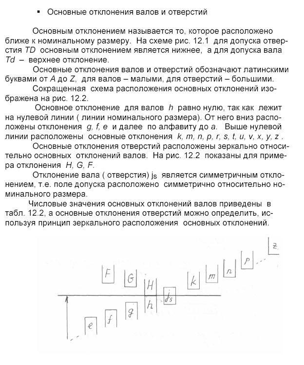
Tolerance field– field limited by upper and lower deviations. It is determined the value of the tolerance and its position relative to the nominal size. In a graphical representation (Fig. 4.6), the tolerance field is enclosed between two lines corresponding to the upper and lower deviations relative to the zero line.
All tolerance fields for holes and shafts are indicated by letters of the Latin alphabet: for holes (I) – in capitals (A, B, C, B, etc.) and for shafts (II) – lowercase (a, b, c, d, etc.). Some of the tolerance fields are designated by two letters. Letters O,W, Q and L are not used.
An example of the location of tolerance fields relative to the nominal size (in the ESDP it is called the zero line) is shown in Figure 4.7.
The nature of the connection of parts in the assembly unit depends on tolerance values details determined by quality, and from location of tolerance fields relative to the zero line, as well as from ratios these parameters.
Figure 4.8 clearly shows how parts that have the same nominal size, but different position of tolerance fields, can be connected with the same quality.
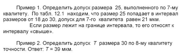
Let us now examine the essence of some concepts. Let's assume that for some part the main design size is set to 25 mm. This is the nominal size. As a result of processing inaccuracies, the actual size of the part may be larger or smaller than the nominal size. However, the actual size should vary only within certain limits. For example, let the largest limit size be 25.028 mm, and the smallest limit size be 24.728 mm. This means that the size tolerance, which characterizes the required processing accuracy of the part, is equal to 25.028–24.728 = 0.300 mm.
As already indicated, on in the drawings indicate not the maximum dimensions, but nominal size and permissible deviations - top and bottom. For the part in question, the upper maximum deviation will be equal to: 25.028–25=0.028 mm; lower limit deviation: 24.728–25=0.272 mm. The part size indicated on the drawing is . The upper limit deviation of the size is written above the lower one. Deviation values are written in smaller font than the nominal size. The plus and minus signs indicate what action needs to be taken to calculate the largest and smallest size limits.
If the lower and upper limit deviations are equal, then they are written as follows: .
In this case, the font size is at the nominal size and at equal absolute values deviations are the same. If one of the deviations is zero, then it is not indicated at all. In this case, the positive deviation is applied in the place of the upper limit, and the minus deviation is applied in the place of the lower limit deviation.
GOST 2.307 – 68* sets general rules applying maximum deviations of linear and angular dimensions of the product.
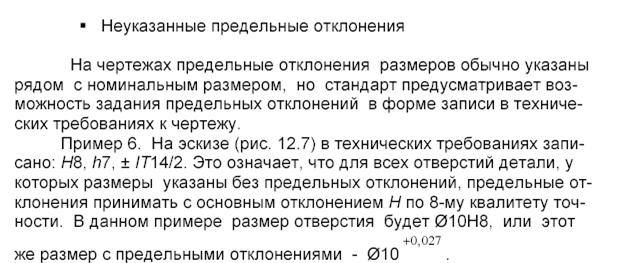
Limit deviations should be indicated immediately after the nominal size , however, it is allowed to indicate numerical values of maximum deviations in a table placed on the free field of the drawing (Fig. 4.9). Maximum deviations of dimensions of relatively low accuracy (from 12th grade and coarser) are not indicated near the nominal size, but are specified by a general entry in the technical requirements of the drawing in accordance with GOST 25670–83 (ST SEV 302–76).
Limit deviations of linear dimensions can be specified in the following three ways:
1. symbols of tolerance fields according to GOST 25346–82 (ST SEV 145–75), for example: Ø 20N7; Ø 20f7 (Figure 2a);
2. numerical values of maximum deviations, for example: Ø 20 +0.021; Ø , (Figure 2b);
3. symbols of tolerance fields indicating on the right in parentheses the numerical values of maximum deviations, for example: Ø 20Н7 (+0.021); Ø , (Figure 2c).
Tolerance fields for holes are indicated in capital letters, and for shafts - in lowercase letters of the Latin alphabet
The digits of the qualification number are written on the same line with the letter and have a height equal to the height of the capital letters.
Maximum deviations are made with a font size one step smaller than the font size of the main value (nominal size), or the same size as the font size of the main value (GOST 2.304–81).
If the nominal dimensions are indicated by letter designations, the tolerance fields must be indicated after the dash: for example, A - H11.
When specifying maximum deviations with numerical values, the upper deviation is indicated above the lower one; deviation equal to zero is not indicated; the symmetrical deviation is indicated once, and the ± signs are placed in front of it.
Number of characters after the decimal point in the upper and lower deviations, expressed as a decimal fraction, should be the same . If necessary, they are aligned by adding zeros.
If maximum deviations are specified in a mixed way - by symbols of tolerance fields and numerical values of maximum deviations, then the latter are taken in brackets.
When indicating the symbols of tolerance fields, it is necessary to provide numerical values of maximum deviations in the following cases:
1. when assigning maximum deviations not included in the series of normal linear dimensions according to GOST 6636–69* (ST SEV 514–77), for example: ;
2. when assigning maximum deviations, the symbols of which are not provided by GOST 25347–82 (ST SEV 144–75) or GOST 25348–82 (ST SEV 177–75), for example, for plastic parts with maximum dimensional deviations according to GOST 25349–82 ( ST SEV 179–75): , (Fig. 4.10, a);
3. when assigning maximum deviations for the sizes of ledges with an asymmetrical tolerance field, for example: (Fig. 4.10, b).
Rice. 4.10 (a, b)
On a surface with one nominal size that has areas with different maximum deviations, the boundary between the areas is drawn with a solid thin line (without intersecting the shaded part of the image), and the nominal size with the corresponding maximum deviations is plotted for each area separately (Fig. 4.11). Maximum deviations of angular dimensions are indicated only by numerical values (Fig. 4.12). The maximum deviations of the dimensions of the parts shown in the assembly drawing (fitting) are indicated in the form of a fraction: in the numerator - the maximum deviations of the hole, in the denominator - the maximum deviations of the shaft.
Maximum deviations in the dimensions of mating elements (in assembly units) are applied in three ways:
1. in the numerator – symbol hole tolerance field, in the denominator - symbol of the shaft tolerance field (Fig. 4.13, a)
2. in the numerator - the numerical values of the maximum deviations of the hole, in the denominator - the numerical values of the maximum deviations of the shaft (Fig. 4.13, b)
3. in the numerator - the symbol of the tolerance field of the hole with the numerical values of the maximum deviations of the hole indicated on the right in parentheses, in the denominator - the symbol of the tolerance field of the shaft with the numerical values of the maximum deviations of the shaft indicated on the right in parentheses (Figure 4.13, c)
Rice. 4.13 (a, b, c)
It is allowed in the drawings of assembly units to show maximum dimensional deviations of only one of the mating parts, without using any additional characters, for example, holes for rolling bearings (Fig. 4.14). If necessary, the drawing explains which part the deviation relates to (Fig. 4.15).
When it is necessary to specify only one limit size (the second is limited in the direction of increase or decrease by some condition), after dimensional number indicate max or min respectively (Fig. 4.16).
If it is necessary to limit fluctuations in the size of identical elements of one part within part of the tolerance (Fig. 4.17) or to limit the accumulated error in the distance between repeating elements (Fig. 4.18), then these data are indicated in the technical requirements.
General entries in the technical requirements must comply with the instructions of GOST 25670–83 (ST SEV 302–76) for applying maximum deviations of linear dimensions, corner dimensions, radii of curvature and chamfers.
In conclusion, we emphasize that for all as-built dimensions of the drawing, maximum deviations must not be indicated without fail.
Surface roughness
Modern technologies It is impossible to achieve absolutely smooth surfaces of manufactured products.
Roughness surface is the totality of all micro-irregularities that form the surface relief of a part. The amount of roughness is determined by the height of the scallops and the depth of the depressions. It has a significant impact on the performance characteristics of parts - friction, wear resistance, strength, etc.
Of course, that roughness product surfaces depends on the technology (method of) obtaining (processing) these surfaces.
GOST 25142-82 allows you to take into account the properties of surface roughness from a unified position, regardless of how you get it (casting, pressing, rolling, chipping, cutting, etc.). This GOST was developed to improve the quality of products. The higher the requirements for surface quality, the more expensive its production.
Correct purpose designer of surface roughness corresponding to the operating conditions of the part, is of great importance in mechanical engineering.
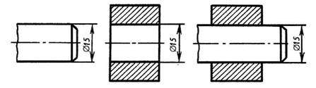
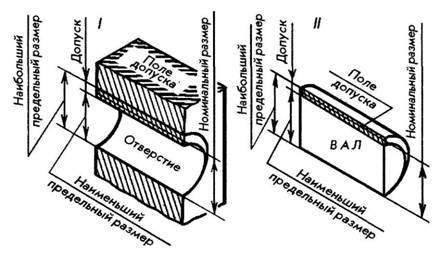
Basic concepts. In the connection of two parts that fit into one another, a female and male surface are distinguished. The most common in mechanical engineering are connections of parts with smooth cylindrical (I) and flat parallel (II) surfaces. For cylindrical joints, the hole surface covers the shaft surface. The covering surface is called hole, covered - shaft. The names “hole” and “shaft” are conventionally applied to other non-cylindrical male and female surfaces (Fig. 115).
Rice. 115
On the working drawings, first of all, dimensions are put down, which quantitatively evaluate the geometric parameters of the parts.
Size- this is the numerical value of a linear quantity (diameter, length, height, etc.). Dimensions are divided into nominal, actual and limiting.
Nominal size(Fig. 116) is the main size of the part, calculated taking into account its purpose and the required accuracy. The nominal size of connections is the common (same) size for the hole and shaft that make up the connection. The nominal dimensions of parts and connections are not chosen arbitrarily, but according to GOST 6636-69 “Normal linear dimensions”. In production, nominal dimensions cannot be maintained: actual dimensions always differ more or less from the nominal ones. Therefore, in addition to nominal (calculated), actual and maximum dimensions on parts are also distinguished.
Rice. 116
Actual size - the size obtained as a result of measuring the finished part with an acceptable degree of error. The permissible inaccuracy in the manufacture of parts and the required nature of their connection are established by means of maximum dimensions.
Limit sizes are two boundary values between which the actual size must lie. The larger of these values is called the largest limit size, the smaller - the smallest limit size (Fig. 117,I). Thus, to ensure interchangeability in the drawings, it is necessary to indicate maximum dimensions instead of nominal ones. But this would greatly complicate the drawings. Therefore, it is customary to express the maximum dimensions in terms of deviations from the nominal.
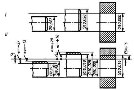
Rice. 117
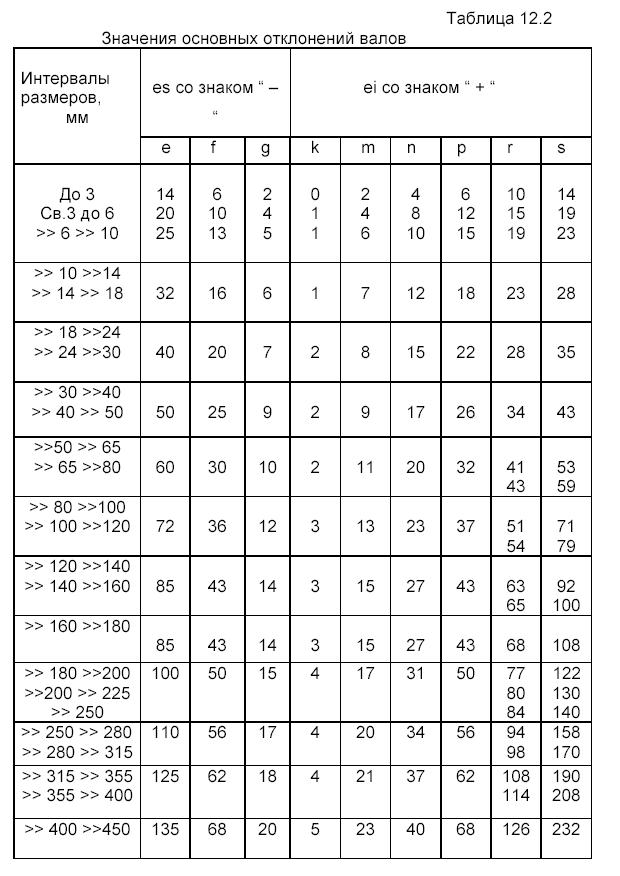
Maximum deviation is the algebraic difference between the maximum and nominal sizes. There are upper and lower limit deviations. The upper deviation is the algebraic difference between the largest limit size and the nominal size. In accordance with GOST 25346-89, the upper deviation of the hole is designated ES, the shaft - es. The lower deviation is the algebraic difference between the smallest limit size and the nominal size. The lower deviation of the hole is designated EI, the shaft - ei.
The nominal size serves as the starting point for deviations. Deviations can be positive, negative and equal to zero (see Fig. 117, II). In tables of standards, deviations are indicated in micrometers (µm). In drawings, deviations are usually indicated in millimeters (mm).
Actual deviation- algebraic difference between real and nominal sizes. A part is considered suitable if actual deviation the size being checked is between the upper and lower deviations.
Tolerance, tolerance range, accuracy standards. Tolerance T * - the difference between the largest and smallest limit sizes or the absolute value of the algebraic difference between the upper and lower deviations.
The GOST 25346-89 standard establishes the concept of “system tolerance” - this is a standard tolerance established by a system of tolerances and landings. Tolerances of the ESDP system** are designated: IT01, ITO; IT1 ... IT17, The letters IT indicate “ISO tolerance” ***. Thus, IT7 denotes approval according to the 7th ISO qualification.
The tolerance value does not fully characterize the processing accuracy. For example, at the shaft? 8_0.03 mm and shaft?64_0.03 mm the tolerance value is the same and equal to 0.03. But it is much more difficult to process a 64_0.03 mm shaft than an 8_0.03 mm shaft.
Tolerance unit i (I) is set as a unit of accuracy, which can be used to express the dependence of accuracy on diameter d. The more tolerance units contained in a system tolerance, the larger the tolerance and therefore the lower the accuracy, and vice versa. The number of tolerance units contained in the system tolerance is determined by the accuracy grade.
Under quality refers to a set of tolerances that vary depending on the nominal size. Qualities cover the tolerances of mating and non-mating parts. To standardize various levels of dimensional accuracy from 1 mm to 500 mm, 19 qualifications have been established in the ESDP system: 01; 0; 1; 2 ... 17.
Currently, the tolerances of measuring instruments and devices are IT01 - IT7, the tolerances of dimensions in fits are IT3 ... IT13, the tolerances of non-critical dimensions and dimensions in rough connections are IT14 ... IT17. For each qualification, based on the tolerance unit and the number of tolerance units, a series of tolerance fields are naturally constructed.
Tolerance field - a field limited by upper and lower deviations. It is determined by the size of the tolerance and its position relative to the nominal size. In a graphical representation (Fig. 118), the tolerance field is enclosed between two lines corresponding to the upper and lower deviations relative to the zero line.
Rice. 118
All tolerance fields for holes and shafts are indicated by letters of the Latin alphabet: for holes (I) - uppercase (A, B, C, B, etc.) and for shafts (II) - lowercase (a, b, c, d and etc.). A number of tolerance fields are indicated by two letters, and letters O, W, Q and L are not used.
Let us now examine the essence of some concepts. Let’s assume that for some part the main design size is set to 25 mm. This is the nominal size. As a result of processing inaccuracies, the actual size of the part may be larger or smaller than the nominal size. However, the actual size should vary only within certain limits. Let, for example, let the largest limit size be 25.028 mm, and the smallest limit size be 24.728 mm. This means that the size tolerance, which characterizes the required processing accuracy of the part, is equal to 25.028-24.728 = 0.300 mm.
As already indicated, the drawings indicate not the maximum dimensions, but the nominal size and permissible deviations - upper and lower. For the part under consideration, the upper limit deviation will be equal to: 25.028-25 = 0.028 mm; lower limit deviation: 24.728-25=0.272 mm. The size of the part indicated on the drawing - The upper limit deviation of the size is written above the lower one. Deviation values are written in smaller font than the nominal size. The plus and minus signs indicate what action needs to be taken to calculate the largest and smallest limit sizes.
If the lower and upper limit deviations are equal, then they are written as follows: .
In this case, the font size of the nominal size and equal absolute values of deviations are the same. If one of the deviations is zero, then it is not indicated at all. In this case, the positive deviation is applied in place of the upper limit, and the negative one - in the place of the lower limit deviation.
* Initial letter French word Tolerance - tolerance.
**Unified system of admissions and landings (USDP).
***International Organization for Standardization (ISO), whose recommendations formed the basis of the ESDP.