
Hole tolerance designation. Landings in the ESDP and their designation in the drawings
System of admissions and landings called a naturally constructed set of standardized tolerances and maximum deviations dimensions of parts, as well as fits formed by holes and shafts having standard maximum deviations.
The standard provides for the use of two systems of tolerances and fits: the hole system and the shaft system.
B hole system the maximum hole dimensions for all fits of the same class are constant, and different fits are obtained by changing the dimensions of the shaft (the hole is unchanged, but the shaft changes and due to this the required clearances or interferences are obtained)
In the shaft system maximum dimensions the shafts are the same for all fits of a given class, and different fits are created by changing the maximum dimensions of the hole (the shaft does not change, but the hole changes).
Due to the fact that it is much easier to process a shaft and it is much cheaper to achieve the required dimensional accuracy for a shaft, our factories have adopted the hole system as the main one.
Designation of landings
The fit is formed by a combination of the hole tolerance field and the shaft tolerance field. The designation of the fit is given in the form of a fraction (Fig. 4, a), where the numerator indicates the tolerance field of the hole, and the denominator indicates the designation of the shaft tolerance field, for example:
;

 ; or H8/
f7;
F8/
h7.
; or H8/
f7;
F8/
h7.
Fit is used in the hole system (preferably) and in the shaft system.
Examples of designation of fits in a hole system:
 ;
;
 ;
; ;
;
 .
.
Examples of similar fits in the shaft system:
 ;
;
![]() ;
; ;
; .
.
In Fig. 4, b shows the form of designation of the fit in the drawing of the connection of two parts.
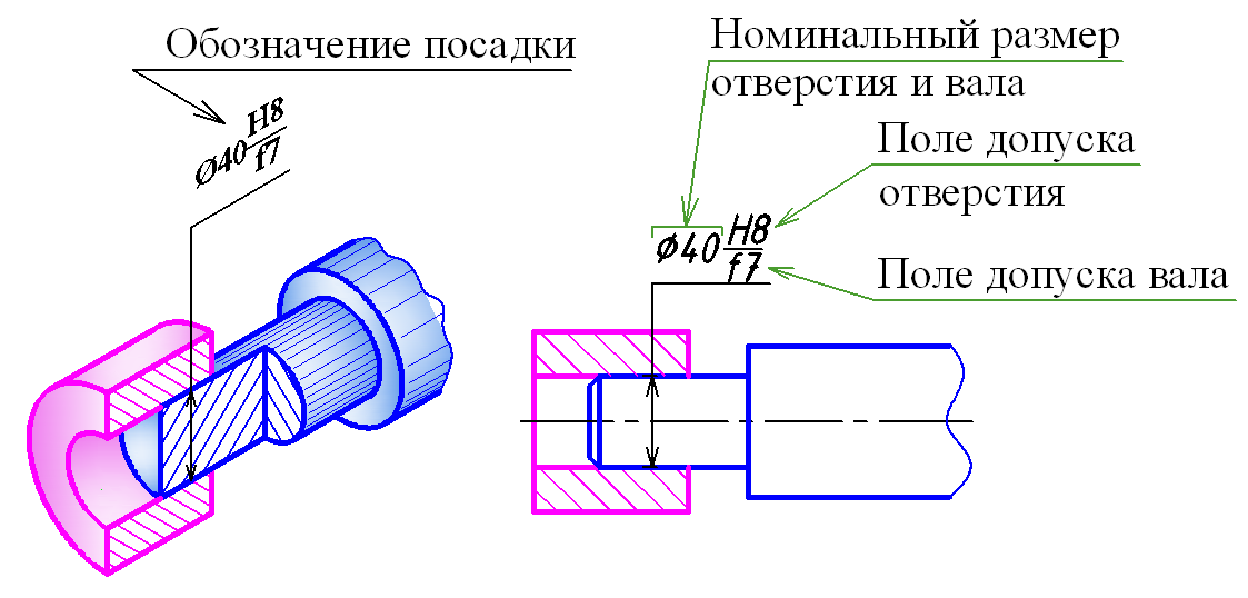
Rice. 4. Landing designation structure
Designation of tolerance fields
The symbol of the tolerance field consists of the letter of the main deviation and a number - the quality number.
Examples of tolerance fields for holes H6, D8, S9; for shafts h6, d8, s9.
Drawing of maximum dimensional deviations on drawings of parts
GOST 2.307-68 establishes the following methods for applying maximum dimensional deviations on drawings of parts:
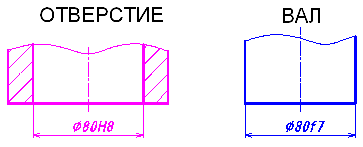
1. Maximum deviations are specified by the tolerance field (Fig. 5).
2. Maximum deviations are indicated by numerical values:
a) with asymmetrical deviations (Fig. 6);
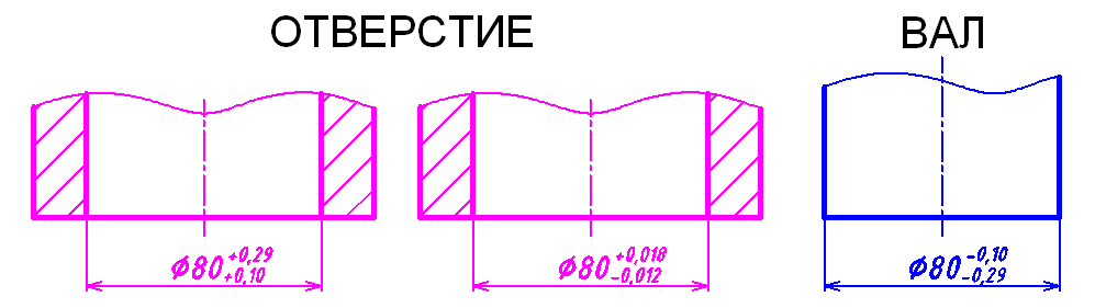
Note. The number of decimal places in the designation of the upper and lower size deviations must be the same.
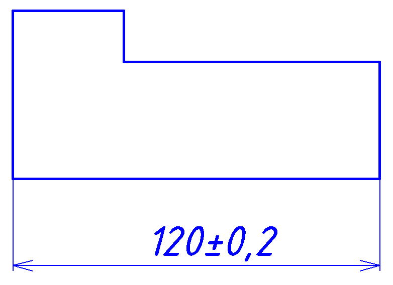
b) if the upper or lower deviation is zero, the zero is not indicated (Fig. 7).
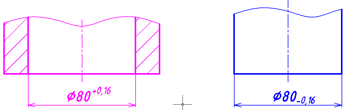
c) with symmetrical deviations (Fig. 8);
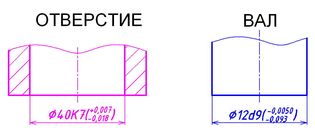
3. Maximum deviations are indicated by a tolerance field and numerical values (Fig. 9).
4. Limit deviations of linear dimensions that are repeated many times in the drawing are recorded as part of the technical requirements (Fig. 10). The recording form is as follows: “Unspecified maximum deviations of dimensions H14, h14, ±IT14/2” or simply “H14, h14, ±IT14/2”.
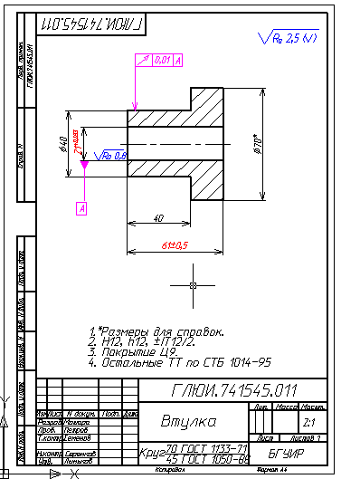
Rice. 10. Example of a working drawing of a part
Holes in the system various fits are formed by a combination of the entire set of shaft tolerance fields presented in Fig. 3.10, with only one hole tolerance field - the tolerance field of the main hole (with the main deviation H).
In the shaft system fits are formed by combining the entire set of tolerance fields of the hole with one shaft tolerance field from the entire set of shaft tolerance fields - the tolerance field of the main shaft (with the main deviation h).
On assembly drawings of landing are indicated by a fraction represented by a combination of numbers and letters of the Latin alphabet (Fig. 3.11).
Designation zones are indicated by corresponding numbers.
Zone 1. In this zone, the diameter sign is indicated - Ø, if the mating parts have a cylindrical surface.
Zone 2. In this zone the value of the nominal size in mm is indicated (in Fig. 3.11 nominal size – 45).
Zone 3. In this zone, the deviation for the hole is indicated in capital letters (in Fig. 3.11 this is the letter H).
Zones 4 and 6. In these zones, the serial numbers of quality are indicated for the hole and shaft, respectively (in Fig. 3.11 for the hole - 7, and for the shaft - 6).
Zone 5. In this zone, the deviation for the shaft is indicated in lowercase letters (in Fig. 3.11 this is the letter k).
In the hole system in zone 3, the designation of the main hole must always be indicated - H. In the shaft system in zone 5, the designation of the main shaft must be indicated – h.
Zones 7 and 8. These zones indicate the maximum deviations for the hole. In zone 7 there is an upper deviation (in Fig. 3.11 the upper deviation is +0.025 mm), in zone 8 there is a lower deviation (in Fig. 3.11 the lower deviation is 0 mm).
Zones 9 and 10. These zones indicate the maximum deviations for the shaft. In zone 9 there is an upper deviation (in Fig. 3.11 the upper deviation is + 0.018 mm), and in zone 10 there is a lower deviation (in Fig. 3.11 the lower deviation is + 0.002 mm). If the maximum deviation is zero, then it is not indicated on the drawing. Maximum deviations on assembly drawings are rarely indicated and only to avoid reference to reference literature when developing drawings of parts.
Examples designations of landings on assembly drawings
Holes in the system
Or ![]() , or
, or  .
.
Here Ø is the sign of the diameter, indicating that the mating parts have a cylindrical surface; 45 – nominal size, mm; H – main hole (main deviation for the hole). The presence of this letter in the numerator indicates that the fit is made in the hole system; 7 – quality for the hole; k – main deviation for the shaft; 6 – quality for the shaft. The lower limit deviation for the main hole is zero. Therefore, there is a space in the numerator in the first line from the bottom. The smallest limit hole size is equal to the nominal one - 45 mm. The upper limit deviation for the hole is +0.025 mm. The "+" sign indicates that with this deviation the hole diameter increases. Therefore, the largest maximum hole size is 45.025 mm . The lower limit deviation for the shaft is +0.002 mm, the upper limit deviation is +0.018 mm. Therefore, the smallest maximum shaft diameter is 45.002 mm, and the largest maximum diameter is 45.018 mm.
In the shaft system
Here G is the main deviation for the hole: 7 – quality for the hole; h – main shaft (main deviation for the shaft); 6 – quality for the shaft.
To transfer fits from one system to another, the qualities of the hole and shaft are maintained, and the main deviations are replaced, for example:
Ø40 G7/h6→Ø40 H7/g6.
These landings are exactly the same in their characteristics, because...
![]() |
| ![]()
maximum hole diameter (D max)
40.034 mm | 40.025 mm
minimum hole diameter (D min)
40.009 mm | 40.0 mm
maximum shaft diameter (d max)
40.0 mm | 39.991 mm
minimum shaft diameter (d min)
39.984 mm | 39.975mm
maximum clearance between hole and shaft (D max – d min)
40.034 – 39.984 = 0.05 mm | 40.025 – 39.975 = 0.05 mm
minimum clearance between hole and shaft (D min – d max)
40.009 – 40.0 = 0.009 mm | 40.0 – 39.991 = 0.009 mm.
System of admissions and landings is a naturally constructed set of standardized tolerances and maximum deviations of the dimensions of parts, as well as fits formed by holes and shafts that have standard maximum deviations.
The standard provides for the use of two systems of tolerances and fits: the hole system and the shaft system.
B hole system the maximum hole dimensions for all fits of the same class are constant, and different fits are obtained by changing the dimensions of the shaft (the hole is unchanged, but the shaft changes and due to this the required clearances or interferences are obtained)
In the shaft system the maximum dimensions of the shaft are the same for all fits of a given class, and different fits are created by changing the maximum dimensions of the hole (the shaft does not change, but the hole changes).
Due to the fact that it is much easier to process a shaft and it is much cheaper to achieve the required dimensional accuracy for a shaft, our factories have adopted the hole system as the main one.
Designation of landings
The fit is formed by a combination of the hole tolerance field and the shaft tolerance field. The designation of the fit is given in the form of a fraction (Fig. 4, a), where the numerator indicates the tolerance field of the hole, and the denominator indicates the designation of the shaft tolerance field, for example:
;
; or H8/
f7;
F8/
h7.
Fit is used in the hole system (preferably) and in the shaft system.
Examples of designation of fits in a hole system:
;
;;
.
Examples of similar fits in the shaft system:
;
![]() ;;.
;;.
In Fig. 4, b shows the form of designation of the fit in the drawing of the connection of two parts.
Rice. 4. Landing designation structure
Designation of tolerance fields
The symbol of the tolerance field consists of the letter of the main deviation and a number - the quality number.
Examples of tolerance fields for holes H6, D8, S9; for shafts h6, d8, s9.
Drawing of maximum dimensional deviations on drawings of parts
GOST 2.307-68 establishes the following methods for applying maximum dimensional deviations on drawings of parts:
1. Maximum deviations are specified by the tolerance field (Fig. 5).
2. Maximum deviations are indicated by numerical values:
a) with asymmetrical deviations (Fig. 6);
Note. The number of decimal places in the designation of the upper and lower size deviations must be the same.
b) if the upper or lower deviation is zero, the zero is not indicated (Fig. 7).
c) with symmetrical deviations (Fig. 8);
3. Maximum deviations are indicated by a tolerance field and numerical values (Fig. 9).
4. Limit deviations of linear dimensions that are repeated many times in the drawing are recorded as part of the technical requirements (Fig. 10). The recording form is as follows: “Unspecified maximum deviations of dimensions H14, h14, ±IT14/2” or simply “H14, h14, ±IT14/2”.
Rice. 10. Example of a working drawing of a part