
How to determine the nominal size. Nominal sizes
The dimensions of the parts that make up the assembly unit depend on the assignment and option for the course work. To determine their nominal values, it is necessary to calculate the scale factor. It is calculated as follows. In the drawing of the course work assignment, the size corresponding to the diameter of the shaft under the rolling bearing (d 3 measured) is measured. The target size (d 3 given) is divided by this measured size to obtain the scale factor μ
By measuring all other dimensions of the parts of the assembly unit and multiplying them by this scale factor, the calculated dimensions are determined.
To reduce the number of standard sizes of workpieces and parts, cutting and measuring tools, the values of nominal dimensions obtained by calculation must be rounded to the values specified in GOST 6636-69 “Normal linear dimensions” (Table A.1). After this, the rounded values of nominal sizes should be entered in Table 1.1. The dimensions associated with the rolling bearing should be taken according to the standard for this product, regardless of the design size. To do this, you should decipher the symbol of a given rolling bearing, determining its series, type and design features, and then, according to GOST 520-2002 or reference books, write down all the parameters of the rolling bearing necessary for further calculations (connecting diameter of the outer ring, width of the rings, dynamic load capacity of the bearing ).
Then the dimensions associated with the rolling bearing are assigned. These dimensions are size d 1 (fitting diameter of the through bearing cap), d 2 (diameter of the hole in the housing for installing the bearing), d 4 (inner diameter of the spacer sleeve), d 5 (fitting diameter of the blind bearing cap). Designations according to .
For example, if according to the assignment it is known that d 3 = 30 mm, bearing type 7300, then this means that the bearing size is 7306 (d 3 /5 = 30/5 = 6), tapered roller bearing and its outer diameter D = 72 mm . In accordance with this, the dimensions d 1 = d 2 = d 5 = 72 mm, and d 4 = d 3 = 30 mm.
When filling out Table 1.1, you should pay attention to the dimensions of standardized and standard parts, which must also be accepted in accordance with the relevant regulatory documents. Such parts include seals of bearing units, keys, round spline nuts, through and blind bearing caps, bearing cups.
Based on the obtained dimensions, an assembly unit is drawn on the appropriate scale.
2 General information about dimensions, tolerances, fits and maximum deviations
Size– numerical value of a linear quantity (diameter, length, etc.) in selected units of measurement. In the drawings, all linear dimensions are indicated in millimeters.
Actual size– element size established by measurement with permissible error.
Limit dimensions– two maximum permissible sizes, between which the actual size of a suitable part must be or can be equal to. The larger one is called the largest limit size, and the smaller one is called the smallest limit size. They are designated D max and D min for the hole and d max and d min for the shaft.
Nominal size– the size relative to which deviations are determined. The size indicated in the drawing is nominal. The nominal size is determined by the designer as a result of calculations for strength and rigidity or taking into account design and technological features. For parts forming a landing connection, the nominal size is common.
IN
Table 1.1 - Assembly unit dimensions Size designation Dimensions measured, mm Design size, mm Size according to GOST 6636-69
upper deviation ES, es – algebraic difference between the largest limit and the corresponding nominal sizes.
ES = D max – D - for hole, (2.1)
es = d max – d - for the shaft. (2.2)
Lower deviation EI, ei – algebraic difference between the smallest limit and the corresponding nominal sizes.
EI = D min – D - for hole, (2.3)
ei = d min – d - for the shaft. (2.4)
Actual deviation– algebraic difference between real and nominal sizes.
Tolerance T – the difference between the largest and smallest maximum dimensions or the algebraic difference between the upper and lower deviations.
T D = D max – D min = ES - EI - for holes, (2.5)
T d = d max – d min = es - ei - for the shaft. (2.6)
Tolerance is always positive. It determines the permissible dispersion field of the actual dimensions of suitable parts in a batch, that is, the specified manufacturing accuracy.
Tolerance field– a field limited by the largest and smallest limit sizes and determined by the tolerance value T and its position relative to the nominal size. In a graphical representation, the tolerance field is enclosed between two lines corresponding to the upper and lower deviations relative to the zero line (Figure 2.1).
Main deviation– one of two deviations (upper or lower), determining the position of the tolerance field relative to the zero line. The main one is the deviation closest to the zero line. The second deviation is determined through tolerance.
Zero line– a line corresponding to the nominal size, from which dimensional deviations are plotted when graphically depicting tolerances and fits.
Shaft– a term conventionally used to designate the external (male) elements of parts, including non-cylindrical elements.
Hole– a term conventionally used to designate the internal (encompassing) elements of parts, including non-cylindrical elements.
Hole tolerance denoted T D, and the shaft T d. In addition to female and male elements called holes and shafts, parts contain elements that cannot be attributed to either a hole or a shaft (ledges, distances between the axes of holes, etc.).
Landing- the nature of the connection of two parts, determined by the difference in their sizes before assembly. The fit characterizes the freedom of relative movement of the parts being connected or the degree of resistance to their mutual displacement. Based on the nature of the connection, three groups of fits are distinguished: fits with clearance, fits with interference, and transitional fits.
Gap S is the difference between the sizes of the hole and the shaft, if the size of the hole is larger than the size of the shaft. The gap allows relative movement of the assembled parts. The largest, smallest and average gaps are determined by the formulas:
S max = D max – d min = ES - ei; (2.7)
S
Figure 2.1. a – pairing b – diagram of the location of the tolerance fields of the shaft and hole
S m = (S max + S min)/2. (2.9)
Preload N is the difference between the dimensions of the shaft and the hole before assembly, if the size of the shaft is larger than the size of the hole. The tension ensures the mutual immobility of the parts after their assembly. The maximum, minimum and average tension are determined by the formulas:
N max = d max – D min = es - EI; (2.10)
N min = d min – D max = ei -ES; (2.11)
N m = (N max + N min)/2. (2.12)
Clearance fit– a fit that ensures clearance in the connection (the tolerance field of the shaft is located below the tolerance field of the hole or touches it at S min = 0) Figure 2.2.
Interference fit– a fit that ensures interference in the connection (the tolerance field of the shaft is located above the tolerance field of the hole or touches it at N min = 0) (see Figure 2.2).
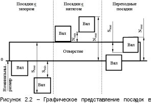
Transitional fit– a fit in which it is possible to obtain both a gap and an interference fit (the tolerance fields of the hole and shaft overlap completely or partially) (see Figure 2.2).
Fit tolerance– the sum of the tolerances of the hole and shaft making up the connection:
T (S, N) = T D + T d –. in general form, (2.13)
T N = N max – N min - for interference fit, (2.14)
T S = S max – S min - for clearance fit. (2.15)
In transitional fits, the fit tolerance is determined as the sum of the largest interference and clearance:
T (S,N) = N max + S max. (2.16)
Example. In a shaft-hole type interface 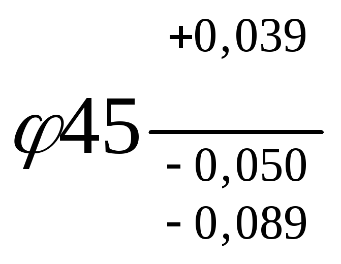 the nominal size of the mate, the maximum deviations of the hole and shaft are known. Determine the maximum dimensions of the hole and shaft, hole tolerance, shaft tolerance, fit tolerance, largest and smallest gaps, construct a diagram of the location of mating tolerance fields indicating deviations.
Solution.
Limit dimensions of the hole (equations 2.1 – 2.2):
largest D max =D + ES = 45 + 0.039 = 45.039 mm;
smallest D min = D + EI = 45 + 0 = 45,000 mm.
Limit shaft dimensions (equations 2.3 – 2.4):
largest d max = d + es = 45 + (-0.050) = 44.950 mm;
smallest d min = d + ei =45 + (-0.089) = 44.911 mm.
Bore tolerance, shaft tolerance and fit tolerance (Equations 2.5, 2.6, 2.13):
T D = ES - EI = +0.039 – 0 = 0.039 mm = 39 µm,
T d = es - ei = - 0.050 – (-0.089) = 0.039 mm = 39 µm,
T S = T D + T d = 0.039 + 0.039 = 0.078 mm = 78 µm.
Largest and smallest gaps (equations 2.7, 2.8):
S max = ES – ei = +0.039 – (- 0.089) = 0.128 mm = 128 µm,
S min = EI – es = 0 – (- 0.050) = 0.050 mm = 50 µm.
The layout of tolerance fields is shown in Figure 2.3.

Preparation of working drawings. Regardless of the structural and technological type of the part, its drawing must be drawn up in compliance with the requirements of standards defining formats (GOST 2.30-1-68), scales (GOST 2.302-68), lines (GOST 2.303-68), fonts ( GOST 2.304-81), designations of graphic materials and rules for their application on drawings (GOST 2.306-68).
Images and designations of the part shape. The working drawing must contain the required number of images and dimensions that determine the shape of the part. Images should convey the shapes of the external and internal surfaces of the part with the greatest expressiveness and on a convenient scale. The working drawing must meet the general requirements established by the ESKD standards.
Images and symbols of materials. The material from which the part is made must be graphically indicated in the drawing on all sections and sections of the part. In some cases, the front side of the material, the direction of the fibers, the base, etc. must be indicated. The name of the material, its brand, grade, GOST and other information must be indicated in the title block.
Indication of the condition of the material. Requirements for the material and. its quality must be specified in the technical requirements. If the material of the part is subject to heat treatment or a coating must be applied to its surface, then appropriate inscriptions must be made about this on the drawing (GOST 2.109-73-basic requirements for drawings, GOST 2.316-68-ESKD. Rules for applying inscriptions and technical requirements on drawings ).
Main inscription, technical requirements. Each drawing contains a title block that must be filled out according to the rules of the ESKD standards. The text part of the technical requirements, inscriptions with the designation of images, designation of product elements and other instructions related to the part or its image are carried out in accordance with ESKD standards.
The general view of the parts must be drawn on sheet A1. The calculation and explanatory note must describe the designed structural parameters of the parts, features of its operation, as well as design calculations.
| When developing a drawing, you need to calculate and select fits, tolerances and deviations for the main interfaces of the device, strictly adhering to the Unified System of Tolerances and Fittings (USDP). All drawings of parts must indicate tolerances and fits, and special manufacturing conditions in accordance with GOST. The drawings are carried out in accordance with the requirements of the ESKD. Execution of working drawings of parts |
| When making working drawings of parts, the main attention should be paid to linking the shape, size and roughness of mating surfaces |
| applied parts and for the development of structural and technological elements of parts. Figure 1 shows examples of the development of structural and technological elements of parts with in various ways connection of parts. The shape and dimensions of structural elements are determined by standards and drawn using appropriate tables. For example, in the image of a threaded connection, grooves and chamfers are not shown, but in images of individual parts, threaded grooves are shown in the main images of the parts. The shape and dimensions of the grooves correspond to the standard. Working drawings of parts must be made taking into account the following requirements: 1. The part on the working drawing is drawn in the same position as it occupies during its manufacture. Body parts and covers with a small number of surfaces subject to machining are allowed to be placed in a position corresponding to the position of the part in the assembly unit. 2. The main view of the part is selected taking into account the following conditions: – as many axes of holes and other elements as possible are oriented parallel to the frontal projection plane, on which |
| 6. Dimensions on mating parts should be placed at the same time to ensure alignment of dimensions. 7. The dimensions of the shape of parts elements are indicated, if possible, in one image, in which this element has a more complete image. The dimensions of the hole diameters are marked on the sections of these holes. The dimensions of non-circular holes and grooves are indicated on those images that show the shape of the holes. 8. The dimensions of the position of the elements of the parts are indicated from the technological and design bases. 9. When determining the dimensions of parts that are taken directly from the image on the general view drawing, you should take into account the scale of the image of the general view drawing. |

Rice. 1. Examples of the development of structural and technological elements
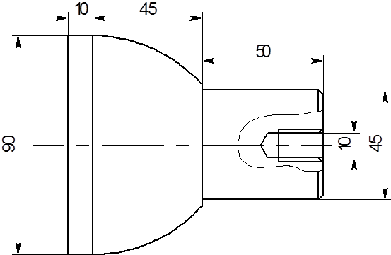
Fig.2. Sketch of the part outline

All dimensions must comply with the requirements of normal linear dimensions. Nominal size is the size relative to which the maximum dimensions are determined and which also serves as the starting point for measuring deviations. For mating parts, the nominal size is common. It is determined by calculations of strength, stiffness, etc., rounded to highest value taking into account “normal linear dimensions”.
Nominal linear dimensions (diameters, lengths, steps, depths, distances between axes, etc.) of parts, their elements and connections must be assigned from among the standard ones in accordance with GOST 6636-69. In this case, the original size value obtained by calculation or other means, if it differs from the standard one, should usually be rounded to the nearest larger standard size. The use of standard nominal sizes provides a great economic effect, as it creates the basis for reducing the standard sizes of products and parts,” as well as technological equipment, primarily dimensional cutting tools, gauges, etc.
Based on a general standard within an industry or an individual enterprise, it is advisable to develop a restrictive standard for normal linear dimensions, which makes it possible to further streamline and reduce the size range of products and tooling, taking into account specific requirements and production conditions. It is especially important to reduce the variety of sizes of mating surfaces, for which the largest number of dimensional equipment is used.
The standard for normal linear dimensions is based on a series of preferred numbers (GOST 8032-56), adopted throughout the world, including in ISO and CMEA standards, as a universal system of numerical values of parameters and sizes of products from all sectors of the national economy. The series of preferred numbers (Tables 1 and 2) are geometric progressions with denominators that in each decimal interval contain 5, 10, 20 and 40 numbers, respectively, which is reflected in the designations of the series.
In addition to the main series of preferred numbers, designated by the letter R, in technically justified cases, it is allowed to use rounded values of some preferred numbers. Series containing numbers of the first rounding are designated, according to the recommendations of ISO and CMEA, with the letter R", and series containing numbers of the second rounding are designated R*. Geometric progression provides a rational gradation of numerical values of parameters and sizes when you need to set not one value, but a uniform series of values in a certain range.In this case, the number of terms in the series is smaller compared to an arithmetic progression.
For these reasons, preferred numbers (usually the series R5, R10 and R 10) are also used when constructing tolerance systems for various dimensional parameters, including tolerances of threads, gears, shape, location and surface roughness.
Selection of normal linear dimensions for part 1, shown in Figure 2.1. Dimensions 50,10, 90 correspond to a number of normal linear dimensions according to Table 1; it is necessary to introduce an adjustment for the values 9.91, 40.09 and 41.08.
In accordance with GOST 6636-69 :
-
Size 9.91 mm, change to 10 mm. (which corresponds to the Ra20 series)
-
Size 90 mm. Let's leave it unchanged. (which corresponds to the Ra20 series)
-
Size 40.09 mm. Let's change it to 45 mm. (which corresponds to the Ra20 series)
-
Size 41.08 mm. Let's change it to 45 mm. (which corresponds to the Ra20 series)
-Size 50 mm. Let's leave it unchanged. (which corresponds to the Ra20 series)
Size 10 mm. Let's leave it unchanged. (which corresponds to the Ra20 series)

1.1 Assignment of tolerances
The tolerance is assigned based on the purpose of the product surface. When selecting and assigning tolerances and fits, the designer always proceeds from the fact that the manufacture of parts to a quality level corresponding to greater accuracy, i.e., with a small tolerance, is associated with an increase in cost due to high labor and material costs for equipment, fixtures, tools and control. But at the same time, high accuracy of connections and high performance indicators of the product as a whole are ensured.
Manufacturing parts according to quality standards with extended tolerances is simpler and does not require precise equipment and finishing technological processes, however, the accuracy of the matings and, consequently, the durability of the machines is reduced.
Thus, designers are always faced with the task of rationally, on the basis of technical and economic calculations, resolving contradictions between operational requirements and technological capabilities, based primarily on the fulfillment of operational requirements.
In educational practice, it is apparently easier to use the similarity method. At the same time, if clarification is necessary, you should be able to refer to reference tables of standard tolerance values and maximum deviations.
Let's give an example. Suppose that during the work you are performing, it becomes necessary to clarify the nature of the connection of two parts and assign a rational tolerance for each. First, using the table. 10 it is necessary to establish which of the three groups of landings is necessary for this connection to perform its operating function. It should be taken into account that each subsequent letter designation of the main deviation of the gap and interference means, respectively, a decrease in the gap and an increase in interference.
Now let's turn to GOST 25347-82. According to the table contained therein. 17 “Recommended fits in the hole system for nominal sizes from 1 to 500 mm” we select a fit for this joint of two parts, for example, k6. An excerpt from the specified table of the standard is given in table. eleven.

We place the tolerance fields relative to the nominal dimensions as follows: “plus” - for the diametrical dimensions of internal surfaces, “minus” - for the diametrical dimensions of external surfaces, symmetrically - for other dimensions.
The procedure for selecting and assigning accuracy and fit qualities
Choice of accuracy quality. Determining the optimal machining accuracy and choosing the accuracy grade is often a difficult task. When arbitrarily assigning unreasonably high quality with small tolerances, the cost of manufacturing parts increases. When choosing a lower accuracy level, the manufacturing cost decreases, but the reliability and durability of the parts in the assembly decreases.
To solve this problem, it is necessary to take into account not only the nature of the landing of a particular connection and its operating conditions, but also recommendations.
Qualities 5 and 6 are used in particularly precise connections, such as “piston pin - bushing of the upper head of the connecting rod of a car engine”, “crankshaft journals - bearing shells”, etc.
Qualities 7 and 8 are used for connections gear wheels with a shaft, installation of rolling bearings in the housing, cutters on mandrels, etc.
Qualities 9 and 10 are used in those connections where the requirements for accuracy are lower, but for coaxiality and centering they are relatively high (for example, installing a piston ring in the piston groove in height, mounting sprockets on the shaft, etc.).
Qualities 11 and 12 are common in movable joints of agricultural machines, in the fits of frequently removed parts that do not require high centering accuracy, and in welded joints.
Landings with clearance. The nature and operating conditions of mobile connections are varied.
Landings of the H/h group are characterized by the fact that the minimum gap in them is zero. They are used for pairs with high requirements for the centering of the hole and shaft, if the mutual movement of the shaft and hole is provided for during regulation, as well as at low speeds and loads.
The H5/h4 fit is prescribed for connections with high requirements for centering accuracy and direction, in which rotation and longitudinal movement of parts during adjustment is allowed. These landings are used instead of transitional ones (including for replacement parts). For rotating parts they are used only at low loads and speeds.
The H6/h5 fit is prescribed when there are high requirements for centering accuracy (for example, the tailstock quill of a lathe, measuring gears when installed on the spindles of gear measuring instruments)
Fit H7/h6 (preferred) is used for less stringent requirements for centering accuracy (for example, replaceable gears in machine tools, housings for rolling bearings in machine tools, cars and other machines).
Fit H8/h7 (preferred) is prescribed for centering surfaces if manufacturing tolerances can be expanded with slightly lower alignment requirements.
ESDP allows the use of fits of group H/h, formed from tolerance fields of qualifications 9... 12, for connections with low requirements for centering accuracy (for example, for fitting gear pulleys, couplings and other parts on a shaft with a key for transmitting torque , with low requirements for the accuracy of the mechanism as a whole and light loads).
Group H/g landings (H5/g4; H6/g5 and H7/g6 - preferred) have the smallest guaranteed clearance of all clearance landings. They are used for precise moving connections that require a guaranteed but small gap to ensure precise centering, for example, a spool in pneumatic devices, a spindle in dividing head supports, in plunger pairs, etc.
Of all the movable landings, the most common are those of the H/f group (H7/f7 - preferred, H8/f8, etc., formed from tolerance fields of qualifications 6, 8 and 9). For example, the H7/f7 fit is used in sliding bearings of low- and medium-power electric motors, piston compressors, machine tool gearboxes, centrifugal pumps, internal combustion engines, etc.
Landings of group H/e (H7/e8, H8/e8 - preferred, H7/e7 and landings similar to them, formed from tolerance fields of qualifications 8 and
9) provide an easily movable connection during liquid friction. They are used for high-speed rotating shafts of large machines. For example, the first two fits are used for the shafts of turbogenerators and electric motors operating with heavy loads. Landings H9/e9 and H8/e8 are used for large bearings in heavy engineering, freely rotating on gear shafts, and for other parts included in clutches, for centering cylinder covers.
Group H/d landings (H8/d9, H9/d9 - preferred and similar landings formed from tolerance fields of qualifications 7, 10 and 11) are used relatively rarely. For example, the H7/d8 fit is used at high rotation speeds and relatively low pressure in large bearings, as well as in the piston-cylinder interface in compressors, and the H9/d9 fit is used for low precision mechanisms.
Group H/c landings (H7/c8 and H8/c9) are characterized by significant guaranteed clearances, and they are used for connections with low requirements for centering accuracy. Most often, these fits are prescribed for plain bearings (with different temperature coefficients of linear expansion of the shaft and bushing) operating at elevated temperatures (in steam turbines, engines, turbochargers, and other machines in which the clearances are significantly reduced during operation due to the fact that the shaft heats up and expands more than the bearing shell).
Transitional landings. Transitional fits of groups H/js, N/k, N/t, N/p are used for fixed detachable connections in which it is necessary to ensure the centering of replaceable parts or (if necessary) their movement relative to each other. The fits are characterized by the possibility of both gaps and interference appearing in the interface. The immobility of the connection is achieved by additional fastening using keys, pins and other types of fastenings.
Transitional fits are provided only in grades 4...8, and the shaft accuracy in them should be one grade higher than the hole accuracy.
In transitional fits, the greatest interference is obtained by combining the largest maximum shaft size (dmax) and the smallest maximum hole size (Dmin), and the largest clearance is obtained by combining the largest maximum hole size (Dmax) and the smallest maximum shaft size (dmin).
Examples of the purpose of transitional landings are shown in Fig. 1 (a - connection "shaft - gear"; b - connection "piston - piston pin - connecting rod head"; c - connection "shaft - flywheel"; d - connection "sleeve - housing").
 |


For surfaces with a diameter of 90mm. We assign an accuracy rating of 9
We take IT1 equal to 87 µm.
The final tolerance is 0.087 µm.
For size 10mm. the tolerance is 0.036 µm.
For size 50mm. the tolerance is 0.074 µm.
For size 45mm. the tolerance is 0.062 µm.
For size 90mm. the tolerance is 0.087 µm.

Second lecture
Part 1. Interchangeability
Lecture outline
Preamble: The general idea of interchangeability; its presentation in relation to interchangeability in geometric parameters. Size and sizing accuracy as key concepts of interchangeability; features of the geometric dimensions of elements.
Nominal size. Rows of preferred numbers. Actual and maximum sizes. Tolerance, tolerance field.
For any product, a certain set of its parameters is essential, each of which in the physical and technical sense is a quantity that characterizes certain properties of the design, material, process...
For example, for an electric motor we can name its design parameters (overall and connecting dimensions), electrical (supply/control voltages, currents, power consumption), mechanical (shaft torque, rotation speed...).
In relation to any physical quantity (PV), the concept is applied "size ».
Size is the quantitative determination of the physical function inherent in a specific object. The definiteness of the PV is also expressed by its value, that is, an estimate of the size in the form of a certain number of units of measurement. The numerical value of the PV varies depending on the size of the unit of measurement:
14 ounces = 396.9 g;
1 cm = 10 mm = 10 4 µm≈0.3937 inches.
Moreover, the size of the PV itself does not depend on any units of measurement (that is, the size is invariant to the choice of units of measurement).
In this first section of the course, the main attention is paid to interchangeability (B) in terms of geometric parameters, that is, in terms of the linear and angular dimensions of the elements of parts. Let us emphasize that we are talking about accuracy. elements details.
Why will the greatest attention be paid to geometric dimensions, and not to the dimensions of the PV in general? The fact is that length, diameter, thickness and other geometric dimensions are more ambiguous and more difficult to determine than the dimensions of almost any other physical objects (examples with measuring body weight at a certain latitude and altitude of a place, electric current strength, etc.).
It should also be noted that measurements of linear dimensions in mechanical engineering and instrument making account for 80 to 90% of all technical measurements carried out in these industries.
Rdimensionsand their accuracy.
Nominal, actual and limiting sizes.
Characterized by the word "nominal" is usually something in name only; the term itself comes from the Latin nominalis (nominal). The meaning of this word in relation to the dimensions of the elements of parts and mates is as follows: on the drawings (parts, assembly units) they put down nominal dimensions, which are not necessarily the desired ones. In relation to the interface - on the assembly drawing - one nominal size common to the parts of this interface is indicated.
Nominal size , marked on the drawing, serves as the beginning of the deviation count; indicated after the numerical value of the nominal size two maximum deviations, in fact, set two maximum permissible size values.
The nominal size is determined from calculations or selected for design reasons and is rounded to the nearest larger size from a range of normal linear sizes.
IN different areas In natural sciences and technology, sequences of ordered quantities are encountered (and introduced). First of all, this means rows of preferred numbers .
It is generally accepted that the system of preferred numbers was invented in 1886 by the French engineer-captain Charles Renard, who proposed geometric progressions for grading rope diameters. In honor of the inventor, the designations for series of preferred numbers contain the letter R. The denominators of geometric progressions are denoted by the letter Q.
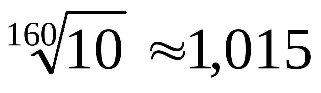
The rows R5;R10;R20;R40 formed in this way are called basic; rows R80; R160 – additional (Table 1); the number after the letter R indicates the number of numbers in the decimal range. Rows with a larger gradation of sizes (with a larger progression denominator) are preferred.
Table 1
|
Basic | ||
|
|
||
|
|
||
|
|
||
|
Additional |
|
|
|
|


The most preferable series R5 found expression in the construction of the “Unified System of Tolerances and Landings”, in particular, in establishing the boundaries of intervals of linear dimensions and choosing a sequence of tolerance values according to qualifications. These issues will be discussed in more detail in the appropriate section.
It is interesting to trace the history of the origin of the series introduced more than 100 years ago by Renard. Is there any other pattern hidden in the structure of these series, other than that inherent in the members of the geometric progression?
Here it is appropriate to recall some historical information.
In ancient times, the “golden” division (“golden” section) of the segment was established:
 or
or  , (1.1)
where L is the length of the entire segment; a is most of it; b is the remaining part of the segment.
The ratio L / a=x can be easily determined from the equation
x 2 –x– 1 = 0, (1.2) which gives x=  ≈
1,62.
≈
1,62.
Frontinus (author of a book written in 97 BC) gave the diameters of the wheels of ancient Roman aqueducts; the gradation of these diameters followed a geometric progression. It is also known that the architects of Byzantium, Hellas, Kievan Rus when determining the ratio of the sizes of their structures, they used a geometric progression with the denominator Q = 1.62.
A geometric progression is also formed by the frequencies of the tones of the musical scale. If the number of steps between frequencies f 0 and 2f 0 (octave) is designated m, then the denominator of the progression is the number Q =  . And to calculate sizes we use the decimal system and, accordingly, Q =
  .
.
Interesting properties of series of preferred numbers are pointed out in the work (for example, the property of equality of extreme and average sums). There are also impressive examples from natural science confirming the connection of these numbers with ordered sequences of some quantities observed in nature. All of the above allows us to conclude: the series of preferred numbers reflect deep patterns inherent in natural phenomena.
So, normal linear dimensions in the range of 0.001 to 20000 mm are built on the basis of series of preferred numbers (Renard series), which are geometric progressions with denominators Q = (see Table 1). The number in the series designation indicates the number of terms of the progression in the decimal interval.
In some cases, rounding of numbers from the above series is required. This is how the series of first and second roundings R / and R // appeared. For example, the numbers 1.5 and 6.0 from the series R // 5 are used instead of the corresponding numbers 1.6 and 6.3 from the series R5.
Actual size physical quantity (PV) – one that is established by measurement with an acceptable error. [The true size is not known, although it exists].
When we measure the capacitance value of a capacitor or, for example, the voltage value at the terminals of an electric battery using an appropriate digital device, we simply read the displayed readings from its display. Weight, pulse frequency, and most other PVs are measured in the same way.
For a linear dimension (length, diameter, height, etc.), determining its actual value is more difficult than for other quantities. The fact is that the elements of the parts are three-dimensional bodies whose shape is not ideal. This can be illustrated in the following figure. 2. Which of the indicated dimensions can be considered the actual length of the bar shown here?
The same ambiguity is manifested in determining the diameter of the shaft, which seems to be round, but is actually irregular in shape (Fig. 3).


In determining the actual size of a part element, attention is paid to connection two elements: the male (conditionally “shaft”) and the female (“hole”), that is, the definition given below “incorporates” the idea of the size of the element under consideration acting in conjunction.
The actual size of a hole or shaft is considered to be the size of the mating part of an ideal geometric shape, adjacent to the surface of the element in question without a gap.
Although the idea of determining the actual size of an element based on an adjacent cylinder is correct in principle (it is this size that will “participate” in the formation of fits), in practice it is difficult to implement it (this idea): there is no reliable and simple way measuring the size of an ideal adjacent element.
All valid sizes must be limited maximum dimensions .
In principle, the whole problem of standardizing the accuracy of any size lies in the need to indicate to the manufacturer (and then to the controller) two maximum permissible values size (FV, part element), beyond which the product becomes unusable:
D min ≤ D d ≤ D max ;
C min ≤ C d ≤ C max …
In practice, it would be very inconvenient to use the maximum size values directly when preparing drawings. To simplify the drawings, maximum deviations from the nominal size have been introduced: top (error super) And lower (error inner) , denoted ES, es and EI, ei for the hole and shaft, respectively.
These deviations are determined by the formulas:
ES = Dmax – D; es = d max – d; (1.3)
EI = Dmin – D; ei = d min – d. (1.4)
The actual deviation is entered in the same way:
E d = D d – D; e d = d d – d. (1.5)
Tolerance, tolerance field
A measure of the accuracy of a size is its tolerance ( Tolerance ) . Tolerance (it is designated T) is the difference between the maximum dimensions (largest and smallest):
T D = D max – D min . (1.6)
This definition of tolerance applies not only to linear or angular dimensions, but also to the dimensions of any other PV. For example, if we are talking about the inductance of the inductor L, then formula (1.6) is written as:
T L = L max – L min .
A broader concept than “tolerance” is “tolerance field”. In general, the term “field” denotes a part of a plane or space where valid something (for example, a conductor carrying current in a magnetic field is acted upon by a directed force in a certain way, the rules of the game of football apply on a football field). The values of actual dimensions included in the tolerance field (as well as deviations) are acceptable and correspond to a suitable part.
According to the well-known definition, the tolerance field is a standardized interval in which the dispersion field of the actual dimensions of suitable parts should be included.
Another definition of the tolerance field is addressed to its graphic representation in the form of a rectangle, limited at the top and bottom by lines of limiting dimensions.
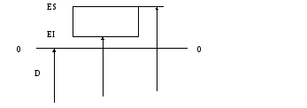
Namely: tolerance field - a zone limited by the largest and smallest maximum dimensions and determined by the value of the tolerance and its position relative to the line of the nominal size(Fig. 4).
Literature
Weil G. Symmetry. – M.: Nauka, 1968.
Fainerman I.D. Regularity of series of preferred numbers // Standards and quality. – 1989. - No. 1 - p. 13 – 15.
Shilov G.E. Simple gamma. Music scale device. - M.: Nauka, 1980.
Markov N.N. Metrological support in mechanical engineering. – M.: “Stankin”, 1995.
Dunin-Barkovsky I.V. Interchangeability, standardization and technical measurements. – M.: Standards Publishing House, 1987. - 352 p.
Belkin V.M. Tolerances and fits (Basic standards of interchangeability). – M.: Mechanical Engineering, 1992.- 528 p.
- How people come to Buddhism and live in it
- Ole nidal Ole nidal as a lama and as a spiritual invalid - the whole truth about the neo-Buddhist sect of kkon
- Modern Spartans. History of ancient Sparta. History of Sparta in the classical era
- Ancient Sparta is one of the most interesting states in history