
Methods for manufacturing gears and gears. Gear and method of its manufacture
Content
Introduction
Purpose course work is not only consolidation, deepening, generalization of knowledge in the main sections and topics of the discipline “Mechanical Manufacturing Technologies”, but also the development of a technological process for manufacturing the “Gear” part.During the course project you must:
- Analyze the design of the part, material, chemical composition and properties of the material, prescribe heat treatment;
Select the production method and type of workpiece;
Develop route technology for processing parts;
Develop operating technology for 3 operations: select equipment and cutting tools, calculate processing modes and time standards;
Calculate the technological cost of the operations being developed.
1. Analysis of initial data
1. 1. Analysis of compliance with the requirements for the manufacture of parts and their intended purpose
Gear (Gear?) - the main part of a gear transmission in the form of a disk with teeth on a cylindrical surface that mesh with the teeth of another gear.The operating principle is based on the engagement of a pair of gear wheel teeth. Classification of gears: according to the relative position of the axes of the gear shafts: with parallel and intersecting axes, according to the arrangement of the teeth: spur, helical, with a circular tooth, according to the shape of the tooth profile: involute and circular
The “Gear” part is made of steel 12Х2Н4А (GOST 4543-71). Steel 12Х2Н4А belongs to alloyed structural steels.
Table 1. Characteristics of material 12Х2Н4А when quenched in oil,
high holiday
Table 2. Chemical composition in % of material 12Х2Н4А
Table 4. Mechanical properties at T=20 o C of material 12Х2Н4А
| V | Thermal change |
||||||
| mm |
MPa |
MPa |
% |
% |
kJ/m2 |
- |
|
| Bar |
F 5 |
1270 |
1080 |
13 |
60 |
1050 |
Delivery status |
| Bar |
F 5 |
980 |
830 |
16 |
70 |
1470 |
Delivery status |
1. 2. Analysis of manufacturability of part design
1. 2. 1. Qualitative analysis of manufacturability
The given gear is one of the gear designs. The part is small, its dimensions are O 102*19, weight is 0.458 kg. This allows processing to be carried out on smaller and, therefore, cheaper machines.The gear undergoes heat treatment, which has great importance in relation to warping that is possible when the part is heated and cooled. In this sense, the jumper connecting the body of the ring gear and the hub is poorly positioned, because During heat treatment, one-sided distortions will occur. The ring gear will decrease in size and cause compression of the hub at the left end. Thus, the hole will take on a conical shape, which will affect the nature of the distortion of the ring gear. The bridge between the crown and the hub should be shifted or tilted, but in this case this is apparently not possible, because The gear has processing on the inner surface of the ring all the way to the jumper.
The round shape of the part indicates its manufacturability when obtaining a workpiece, processing, and control. With the exception of teeth, processing can be carried out on very common machines of the turning and grinding groups.
At the same time, from the point of view of mechanical processing, ZKs are not technologically advanced, because The operation of obtaining teeth and removing chips is carried out mainly by low-productivity methods.
The design of the gear, despite its stepped shape, allows teeth to be processed simultaneously on several parts mounted on a mandrel and using intermediate parts. When machining multiple parts, the time lost associated with inserting cutters is reduced.
Most gear elements are technologically advanced and allow processing with standard purchased tools.
Technological chamfers with a central hole. They do not allow burrs to form on the ends of the hub when pulling a hole or keyway.
The most precise and critical element of the part is the central hole O36 H7 with a roughness of Ra 1.6 microns. The roughness on the teeth is Ra 1.0 µm, so they need to be ground or shaving. The remaining surfaces are made less precisely, their roughness is rougher.
The part has good bases; when processed, it has an O36 H7 hole and an accurate end. These same surfaces are also used as bases for inspection.
The parts have the correct dimensions and technical details. requirements.
Considering the above, the item deserves qualitative assessment Manufacturability of the part design is good.
1. 2. 2. Quantitative analysis of manufacturability
1) Processing accuracy factor,
where A av – average quality of the part
A – processing quality,
n – number of sizes of the corresponding quality.
<0,92 оценка по коэффициенту
«удовлетворительно».
2) Surface roughness coefficient
To determine the coefficient, it is necessary to find the average roughness of the part
K Ra =0.242 – assessment according to the coefficient “good”.
2. Justification of the method and method for obtaining the initial workpiece
The type of workpiece and the method of their manufacture for a specific part are determined by such indicators as:- material;
structural form;
serial production;
workpiece mass.
Group code – 6.
The structural forms of general mechanical engineering parts are divided into 14 types. We select the appropriate code based on a comparison of the real part with the description of typical parts presented in Table 3.2 (1.61 pages).
The gear has a cylindrical surface with a smooth through hole. Therefore, the structural form code is 6.
Production serial code according to table 3.3. (1.62 pages) – 2.
Gear weight 0.458 kg. According to table 3.4. (1.62 pages) range number – 1.
Thus, having determined the codes for each of the four factors, we will compile a list of possible types and methods of obtaining blanks for a given part according to Table 3.7. (1.64 pages):
- stamping on hammers and presses;
stamping on horizontal forging machines.
Let's choose the optimal one in terms of the parameter K them - the coefficient of material utilization:
To them = m children / m zag (2.1)
m zag = m children /K tu, (2.2)
where Kw is the weight accuracy coefficient.
Since K them = K w, it is enough to choose the type of workpiece with the highest weight accuracy coefficient. (, page 63)
Table 5. Methods for obtaining the workpiece
Thus, it is advisable to choose a workpiece obtained by stamping on horizontal forging machines.
According to GOST 7505-89, we will design the workpiece necessary to obtain a given part:
1. Initial data on the part:
1.1. Material – Steel 12Х2Н4А (GOST 4543-71):
- 0.09-0.15% C;
0.17-0.37% Si;
0.3-0.6% Mn;
3.25-3.65% Ni;
0.025% S;
0.025% P;
1.25-1.65% Cr;
0.3% Cu.
2. Initial data for calculation:
2.1. Forging weight – 0.756 kg. (calculated);
Calculated coefficient K p =1.5...1.8 (? 1.65) according to GOST 7505-89.
1.65*0.458=0.756 kg.
2.2. Accuracy class – T4.
2.3. Steel group – M1.
The average mass fraction of carbon in steel 12Х2Н4А is 0.12%;
The total mass fraction of alloying elements is 0.0597% (0.27% Si; 0.45% Mn; 3.45% Ni; 0.025% S; 0.025% P; 1.45% Cr; 0.3% Cu).
2.4. Difficulty level – C2.
Dimensions of the figure describing the forging (cylinder), mm:
Diameter 107.1 (102*1.05=107.1) (where 1.05 is the coefficient).
Height 19.95 (19*1.05=19.95).
The mass of the describing figure (calculated) is 1.401 kg.
G f = ?*D 2 /4*? st *h, where
G f - mass of the describing figure;
D – diameter;
h – height;
? st – steel density.
G f =3.14*107.1 2 *0.25*7.8*10 -6 * 19.95=1.401 kg.
G p: G f = 0.756: 1.401 = 0.54.
2.5. The configuration of the die connector surface is P (flat).
2.6. The original index is 7.
3. Allowance and forging allowances
3.1. Main allowances for dimensions, mm.
1.3 – diameter 107.1 mm and surface finish 5.0;
1.0 – diameter 36 mm and surface finish 12.5;
1.0 – thickness 19 mm and surface finish 2.5;
3.2. Additional allowances taking into account:
Displacement along the surface of the die connector – 0.2 mm;
Deviation from flatness – 0.4 mm.
4. Forging dimensions and their permissible deviations
4.1. Forging dimensions, mm:
Diameter 102+ (1.3+0.2)*2=105 is taken as 105;
Thickness 19 + (1.0+0.4)*2=21.8 is taken as 22;
Permissible deviations of dimensions, mm:
Diameter: Thickness:
Figure 1. Workpiece
3. Process development
3. 1. Development of a processing plan and its description
Figure 2. Establishing positions of part surfaces
Table 6. Establishment of surface treatment stages
| Processing stages |
||||
| 1 |
2 |
3 |
4 |
|
| Rough turning |
Finish turning |
Cementation |
||
| Rough turning |
||||
| Rough turning |
||||
| Rough turning |
||||
| Rough turning |
||||
| Rough turning |
||||
| Reaching out |
||||
| Rough turning |
||||
| Rough turning |
Rough grinding |
Grinding finishing |
||
| Hobbing |
Cementation |
Gear grinding |
||
| Drilling |
||||
| Rough turning |
Grinding rough |
Grinding finishing |
||
| Rough turning |
||||
3. 2. Development of technological operations and transitions
Route Technology OperationsWhen developing route technology, all mechanical processing is distributed among operations and, thus, the sequence of operations and their number are determined. In the conditions of a specific production, equipment is selected for each operation and the design diagram of the device is determined.
Route technology also provides for control in order to technologically ensure the specified quality parameters of the processed part. In this case, the object of control and its place are assigned after those operations in which accuracy is most difficult to ensure.
Route technology for gear machining includes the following operations:
Table 7. Technological route for gear processing
| Transaction number |
Operation name |
Brief description of the operation |
| 000 |
Procurement |
|
| 005 |
Turning |
Sharpen the ends 4, 12 rough. Drill hole 8 into a rough passage. Boring 5, 6. |
| 010 |
Turning |
Sharpen ends 2, 9 rough. Sharpen surface 1 rough. Boring 13, 3. |
| 015 |
Flushing |
|
| 020 |
Control |
|
| 025 |
Turning |
Surface finishing – 1 |
| 030 |
Drilling |
Drilling hole 11 |
| 035 |
Grinding |
Roughly sand the surface 9 |
| 040 |
Grinding |
Sand rough surface 12 |
| 045 |
Galvanic |
Copper plating |
| 050 |
Hobbing |
Mill 32 teeth (m=3) for grinding |
| 055 |
HTO |
Cement only teeth up to 57…59 HRC e |
|
060 |
Grinding |
|
| 065 |
Grinding |
Sand the surface clean |
| 070 |
Reaching out |
Pull the splines 7 |
| 075 |
Gear grinding |
Grind 32 teeth (m=3) |
| 080 |
Flushing |
|
| 085 |
Control |
Procurement operation
Ra v200
Figure 3. Operational sketch of operation 000
Turning operation
Ra v12.5
Figure 4. Operational sketch of operation 005
Turning operation
Ra v12.5
Figure 5. Operational sketch of operation 010
Turning operation
Ra v 5.0
Figure 6. Operational sketch of operation 025
Drilling operation
Ra v12.5
Figure 7. Operational sketch of operation 030
Grinding operation
Ra v2.5
Figure 8. Operational sketch of operation 035
Grinding operation
Ra v2.5
Figure 9. Operational sketch of operation 040
Copper plating
Figure 10. Operational sketch of operation 045
Gear hobbing operation
Ra v12.5
Figure 11. Operational sketch of operation 050
Cementation of teeth up to 57…59 HRC e
Figure 12. Operational sketch of operation 055
Grinding operation
Ra v2.5
Figure 13. Operational sketch of operation 060
Grinding operation
Ra v2.5
Figure 14. Operational sketch of operation 065
Pulling operation
Ra v12.5
Figure 15. Operational sketch of operation 070
Gear grinding operation
Ra v1.6
Figure 16. Operational sketch of operation 075
3. 3. Dimensional analysis of the technological process
Figure 17. Combined circuit
Figure 18. Tree graph
We get the following equations:
- (5) – l6 = 0
(19) – l10 = 0
(5) – l3 = 0
(16) + l2 – l4 + l5 = 0
(1.5) – l5 + l7 – l9 = 0
(Z065) + l10 – l9 = 0
(Z060) + l9 – l8 = 0
(Z040) + l8 – l7 = 0
(Z035) + l7 – l4 = 0
(Z010) + l4 – l1 = 0
(Z005) + l1 – A = 0
When distributing tolerances, it is necessary that each component link has a tolerance corresponding to one or another accuracy grade according to GOST 25347-82, depending on the operation in which a given size is maintained.
0,3 0,075
- T (5) ? T l6
- T (19) ? T l10
- T (5) ? T l3
- T (16) ? T l2 + T l4 + T l5
- T (1.5) ? T l5 + T l7 + T l9
- wZ065 = T l10 + T l9
- wZ060 = T l9 + T l8
- wZ040 = T l8 + T l7
- wZ035 = T l7 + T l4
- wZ010 = T l4 + T l1
- wZ005 = T l1 + T lА
- l 3 = (5) = 5 +0.075
l 6 = (5) = 5 +0.075
l 10 = (19) = 19 -0.033
l9 = (Z065) + l10
where: Rz – surface roughness before processing in this operation;
hc is the depth of the defective layer;
Then: Z065 = 0.025 +0.066 mm.
l9 =
Examination:
Z065 fact. = l9 - l10 = > Z065 calc.
- l8 = (Z060) + l9
l8 =
Examination:
Z060 fact. = l8 – l9 = > Z060 calc.
- l7 = (Z040) + l8
l7 =
Examination:
Z040 fact. = l7 – l8 = > Z040 calc.
- l4 = (Z035) + l7
l4 =
Examination:
Z035 fact. = l4 – l7 = > Z035 calc.
- l1 = (Z010) + l4
l1 =
Examination:
Z010 fact. = l1 – l4 = > Z010 calc.
- A = (Z005) + l1
A=
Examination:
Z005 fact. = A – l1 = > Z005 calc.
- l5 = (1.5) + l7- l9
Examination:
(1.5) fact. = l5 - l7+ l9 = > (1.5) calc.
We appoint
l5 =
Examination:
(1.5) fact. = l5 - l7+ l9 =
1,25 < 1,267…1,393 < 1,5
So l5 =
- l2 = l4 - l5 - (16)
Examination:
(16) fact. = l4 – l5 - l2 =
So l2 =
3. 4. Calculation of operation 025 Turning
Figure 19. Turning operation 025
3. 4. 1. Selection of equipment and cutting tools
For operation 010, a 16B04A screw-cutting lathe was selected, based on the largest diameter of the workpiece being processed above the support.Table 8. Main characteristics of the machine
| Characteristic |
|
| The largest diameter of the workpiece being processed above the bed |
200 |
| The largest diameter of the workpiece above the support |
115 |
| Maximum length of workpiece processed |
350 |
| 320-3200 |
|
| Caliper feed (mm/min) longitudinal |
0,01-0,175 |
| Caliper feed (mm/min) transverse |
0,005-0,09 |
| Main drive electric motor power, kW |
1,1 |
| dimensions |
|
| Length |
1310 |
| Width |
690 |
| Height |
1360 |
| Weight, kg |
1245 |
The cutting tool is a right-hand thrust cutter, bent with a plan angle of 90°, equipped with a plate made of hard alloy TT31K10 in accordance with GOST 18879-73.
Table 9. Cutter parameters
| 25 |
16 |
140 |
7 |
16 |
1,0 |
3. 4. 2. Calculation of cutting conditions
1) Depth of cutWhen the roughness parameter of the machined surface is Ra 3.2 inclusive, t = 0.5...2.0 mm;
Ra? 0.8 µm, t = 0.1…0.4 mm.
When Ra = 12.5 we assign:
Cutting depth 0.5 mm;
Number of passes – 1.
2) Feed
Feeds during finishing turning are selected depending on the required roughness parameters of the machined surface and the radius at the tip of the cutter.
We assign feed s = 0.2 mm/rev.
3) Cutting speed
The cutting speed for external longitudinal and transverse turning and boring is calculated using the empirical formula:
,
T – average durability value, with single-tool processing T=30-60 min. We accept T = 60 min for all surfaces.
The values of the coefficient, exponents x, y, m are determined from the table. (Table 17, Volume 2)
Table 10. Determination of cutting speed
Spindle speed:
(rpm)
4) Cutting force
It is customary to decompose the cutting force into force components directed along the coordinate axes of the machine. For external longitudinal and transverse turning, boring, cutting, slotting and shaped turning, these components are calculated using the formula:
Constant and exponents x, y, n for specific (calculated) processing conditions for each component of the cutting force.
Table 12. Determination of cutting force
Correction factor taking into account the influence of the quality of the processed material:
Table 13. Calculation of the correction factor
Table 14. Cutting forces
| Surface number |
||||||
| 1 |
0,5 |
0,2 |
197,88 |
134,76 |
34,04 |
85,59 |
5) Cutting power
The following condition must be met:
N? N electric motor
0,277 ? 1,1
This condition is met, so the selected machine is suitable.
3. 4. 3. Calculation of time standards
The piece-by-piece processing time of a part is calculated using the formula: ,where: T sh-k – piece-calculation time for processing a part;
T pz – preparatory and final time, min;
n – number of parts in the tuning batch;
T pcs – piece processing time of a part.
The piece processing time of a part is calculated using the formula:
Where: T o – main time;
T in – auxiliary time;
– time for workplace maintenance, rest and breaks.
Basic time is calculated using the formula:
Where: - estimated processing length in the feed direction, mm;
i – number of working strokes in the transition;
- minute feed of the tool in the feed direction, mm/min.
,
where s – feed, mm/rev
n - spindle rotation frequency.
Table 15. Main time
| 0,2 |
617,83 |
123,57 |
1 |
19+2 = 21 |
0,17 |
Auxiliary time is the time for the actions of a worker accompanying the execution of the main technological work.
Where: T u.s. – time for installation and removal;
T zo – time for fastening and unfastening;
T up – time for management;
T from – time for measurements.
Table 17. Auxiliary time
C.
= 0,17+2,29+0,17=2,63
T pz = 6 (min.)
(PC.)
(min.)
3. 4. 4. Determining the cost of performing an operation
Table 18. Initial data| Index |
|
| Machine capacity, machine-minutes (T o) |
0,17 |
| Labor intensity, standard minutes, (T sh-k) |
2,67 |
| Machine operator's work category |
4 |
| Shift |
2 |
| Machine |
16B16A |
| Machine hour factor |
1 |
| Annual program, pcs. |
1000 |
Wholesale price for blanks:
C m = ? – ?*lnm (rub/t), where
m – mass of the workpiece, kg;
i – part complexity group according to the price list;
?, ? – empirical coefficients.
i=2
? = 9 392,4
? = 1 258,6
m = 0.458 kg.
C m = 9392.4 – 1258.6*In0.458= 10375.2 rub./t., where
Workpiece price:
Ts zag = g m * Ts m * k T-3, (rub.), where
g m – consumption rate per part;
g m =0.458;
k T-3 – coefficient of transportation and procurement costs;
k T-3 =1.04;
C zag = 0.458*10 375.2*10 -3 *1.04 = 4.94 (rub.)
Table 19. Cost calculation
| Index |
Indicators |
||
| Machine operator's salary with accruals, kopecks. |
The salary standard for a 4th grade worker with all accruals is 10.86 (kop./min.) Labor intensity – 2.67 (min.) |
10,86*2,67 |
29 |
| Costs of maintaining and operating equipment, kopecks. |
Machine capacity – 0.17 (min.) Machine hour factor – 1 Average costs for 2 shifts and medium-scale production – 7.6 (kop./min.) |
0,17*1*7,6 |
1,29 |
| Processing cost, kopecks. |
29+1,29 |
30,29 |
|
| Cost of procurement, kopecks. |
494 |
||
| Technological cost of the part, kopecks. |
30,29+494 |
524,29 |
3. 5. Calculation of operation 030 Drilling
Ra v12.5Figure 20. Operational sketch of operation 030
3. 5. 1. Selection of equipment and cutting tools
For operation 030, a 2N106P vertical drilling machine was selected, based on the largest drilling diameter in steel.Table 20. Main characteristics of the machine
| Characteristic |
|||||||||||||||||||||||||||||||||||||||||||||||||||||||||||||||||||||||||||||||||||||||||||||||||||||||||||||||||||||||||||||||||||||||||||||||||||||||||||||||||||||||||||||||||||||||||||||||||||||||||||||||||||||||||||||||||||||||||||||||||||||||||||
| Largest drilling diameter in steel |
6 |
||||||||||||||||||||||||||||||||||||||||||||||||||||||||||||||||||||||||||||||||||||||||||||||||||||||||||||||||||||||||||||||||||||||||||||||||||||||||||||||||||||||||||||||||||||||||||||||||||||||||||||||||||||||||||||||||||||||||||||||||||||||||||
| Working surface of the table |
200*200 |
||||||||||||||||||||||||||||||||||||||||||||||||||||||||||||||||||||||||||||||||||||||||||||||||||||||||||||||||||||||||||||||||||||||||||||||||||||||||||||||||||||||||||||||||||||||||||||||||||||||||||||||||||||||||||||||||||||||||||||||||||||||||||
| The greatest distance from the end of the spindle to the working surface of the table |
250 |
||||||||||||||||||||||||||||||||||||||||||||||||||||||||||||||||||||||||||||||||||||||||||||||||||||||||||||||||||||||||||||||||||||||||||||||||||||||||||||||||||||||||||||||||||||||||||||||||||||||||||||||||||||||||||||||||||||||||||||||||||||||||||
| Spindle overhang |
125 |
||||||||||||||||||||||||||||||||||||||||||||||||||||||||||||||||||||||||||||||||||||||||||||||||||||||||||||||||||||||||||||||||||||||||||||||||||||||||||||||||||||||||||||||||||||||||||||||||||||||||||||||||||||||||||||||||||||||||||||||||||||||||||
| Number of spindle speeds |
7 |
||||||||||||||||||||||||||||||||||||||||||||||||||||||||||||||||||||||||||||||||||||||||||||||||||||||||||||||||||||||||||||||||||||||||||||||||||||||||||||||||||||||||||||||||||||||||||||||||||||||||||||||||||||||||||||||||||||||||||||||||||||||||||
| Spindle speed, rpm |
1000-8000 | ||||||||||||||||||||||||||||||||||||||||||||||||||||||||||||||||||||||||||||||||||||||||||||||||||||||||||||||||||||||||||||||||||||||||||||||||||||||||||||||||||||||||||||||||||||||||||||||||||||||||||||||||||||||||||||||||||||||||||||||||||||||||||
|
158
.. 14.4. TECHNOLOGICAL PROCESS OF MANUFACTURING GEARS OF A GEAR PUMP Purpose and design features . The gear pump includes a drive (Fig. 14.3) and a driven gear, which differ from each other by the presence of keyways on one of them. Material and type of workpiece. Gears are made of round steel 95X18 (GOST 5949-75) with a diameter of 27 mm (GOST 2590-71). Manufacturing of gears. Pre-processing of the gear - the formation of a disk with a hole - is carried out on multi-spindle bar automatic lathes and cylindrical grinding machines. The accuracy of the parameters of the resulting gear blank corresponds to 11-12 qualifications. After preliminary heat treatment, a number of technological machining operations are performed: ensuring the specified height of the gear and Preliminary grinding of the end surfaces is carried out on a surface grinding machine on a round magnetic table with restrictive rings. Before installation, the magnetic table and gears are washed and dried with compressed air. Grinding is done first on one side to a size of 5.9+0.05 mm, and then on the other side to a size of 5.8+0.05 mm. The deviation from parallelism of the end surfaces after preliminary grinding should not exceed 0.01 mm. After countersinking a 0.7X45° chamfer and cleaning the 12H11 hole with a reamer on a vertical drilling machine, the gears are demagnetized, cleaned on both sides and blown with compressed air. Rice. 14.3. Drive gear Finishing operations are intended to obtain a given gear height. The gears are first measured with a micrometer and sorted by height into groups (height difference Finishing of the center hole in the gear is carried out on an internal grinding machine. Four parts are processed simultaneously in a special device. The hole is ground to dia. 12.9-0.025 mm, providing a deviation from the perpendicularity of the hole to the end equal to 0.012 mm, surface roughness Ra = 1.25 μm and radial runout of the outer surface relative to the hole of no more than 0.1 mm. The machine spindle speed is 24250 min-1. Parameters are controlled by an indicator and limit gauges. Grinding of gear teeth is carried out in several stages on a 5A830 gear grinding machine. Preliminary grinding of the teeth (t = 0.75 mm; z = 30) is performed to the diameter of the cavities dia. 21.3+0.1 mm with a total normal of 5.828 mm. Runout along the pitch circle is allowed no more than 0.015 mm, radial runout depressions no more than 0.015 mm, tolerance for tooth direction 0.015 mm along the length of the mandrel on which the rods are mounted. The second preliminary grinding reduces the diameter of the depressions to 20.60-0.1 mm with a normal length of 5.828+0.144 mm. The tooth direction tolerance is 0.006 mm. To reduce the radial runout of the outer diameter of the gear teeth, grinding along the outer diameter on a cylindrical grinding machine to dia. 24.14+0.01 mm. Mandrel runout is allowed no more than 0.005 mm. Keyways in gears are made sequentially on horizontal broaching machines 7A510. A broach 3 mm wide is used as a tool. After the formation of one groove, the size is maintained at 14.35+0.1 mm, after the formation of the second groove, the size is 15.8+0.2 mm. After preliminary mechanical treatment, the gears are heat treated to a hardness of HRC 55-60. Hardened gears are sorted into groups with a height difference of 0.01 mm. Then finishing operations are carried out to obtain a given height, which are carried out on a finishing machine using a cast iron plate and a paste containing spindle oil, kerosene and micropowder. The gears for processing are placed in a separator. The rotation speed of the separator is 25 min-1, the finishing discs are 62 min-1. The force of the upper disk during pre-processing is 1500 N. The allowance (0.02 mm) left earlier during preliminary finishing is removed in two steps during final finishing to a size of 5.7-0.0095 mm. The force of the disks during final finishing is 500-700 N. During preliminary and final finishing, the gears are rearranged in the separator slots. After processing, the parts are washed in gasoline, blown with compressed air, and then polished along the outer diameter on a lathe. An internal grinding machine is used to finish the gear bore. The rotation speed of the grinding wheel is 2400 min-1, the processed gear is 480 min-1; feed 0.0025-0.0015 mm/stroke; The radial runout of the workpiece during installation should not exceed 0.005 mm, the end runout should not exceed 0.003 mm. Grinding is carried out in two technological transitions to a diameter of 13+0.027 mm. After processing, the mounting hole is sorted by diameter into three groups: Group I - diameter 13+0.016 mm Group II - diameter +0.023 +0.027 mm, Group III - diameter 13+0.019 mm. Then the surface is finally ground to an outer diameter of 24-0.003 mm. Groups of gears are processed separately. Finishing gear grinding is carried out on a gear grinding machine in two technological transitions. Radial runout of the mandrel for installing gears is allowed no more than After final gear grinding to remove burrs, the part is polished along the outer diameter, washed, dried and controlled for the hole diameter, the length of the common normal and the height of the gear, after which the gears are sent for assembly. Send your good work in the knowledge base is simple. Use the form belowStudents, graduate students, young scientists who use the knowledge base in their studies and work will be very grateful to you. Posted on http://www.allbest.ru/ 1 . Manufacturing technology 1.1 Technological process for manufacturing the part Initial data: The initial data for completing the course project are the part drawing and the annual product production program. Annual program N=12000 pieces. Figure 1.1 - General form gears. 1.2 Purpose of the part The driven gear, which is part of the head of the device for checking threads, is designed to transmit torque from the driving spindle to the driven one. 1.3 Description of the design and conditions of its operation in the mechanism The gear included in the head of the device for checking threads has one crown. The crown is in constant mesh with the drive gear of the drive spindle. 1.4 Part material, mechanical properties and type of maintenance The gear is made of steel 20 GOST1050-74. Gear weight 1.3 kg. Steel 20 has the following mechanical properties: 1) hardness of annealed steel 156 HB; 2) tensile strength 520 MPa; 3) yield strength 260 MPa; 4) relative elongation 26%; 5) relative narrowing 55%; 6) impact strength 11 J/cm; 7) carbon C 0.17…0.23 8) silicon Si 0.17…0.37 9) manganese Mn 0.35…0.65 The surface of the driven gear crown with ? 104 mm is subjected to carburization and hardening to a hardness of 50...54 HRC. 1. 5 Calculation of the batch size of a part Let us determine the size of the batch launched into production simultaneously: where a is the frequency of launching a given part in days; a=24; d - number of working days per year, let’s take d=253; N - annual program; 12000·24/253 = 1138.3 pcs; Let's take the batch size to be 1140 parts. 2 . Design manufacturability analysis 2.1 Choosing a method for obtaining a workpiece The choice of workpiece is made on the basis of a technical and economic analysis. This is done by calculating and comparing the cost C i of various i-th options for obtaining blanks. The total cost and quality of the part consists of the cost and quality of the workpiece and the cost and quality of its processing. Cost calculation is carried out according to the following dependencies: where m from is the mass of the casting, kg m from =5%·m D + m D =1.3·0.05+1.3=1.365kg m D - mass of the part c 1m - price of 1 kg of liquid metal, c 1m = $0.19 C l - cost of foundry work, With l =0.008 m from =0.008 1.365=0.01$ q l - overhead costs of the foundry (q l = 50-100%). Let's take q l =60% C mod - cost of the model, C mod = m from n mod - the number of blanks manufactured using one model B - minute wage workers (B=0.02...0.04, dollars/min). Let's take B=0.03$/min T shk - piece-calculation time T shk =0.01l 0 k=3.2min where l 0 is the processing length, l 0 = 2 110 + 76 +23 = 320 mm k - number of tool passes, k=1 q - overhead costs, q=100% C from =1.365·0.19+0.01·(1+60/100)+ 1.365/12000 +0.03·3.2·(1+100/100)=$0.29 S p =m sh c 1pr +VT shk (1+)+S pcs (1+) where m w is the mass of the rod before stamping, kg (10-30% more than the mass of the finished part) m w =10% m d + m d =1.3 0.1+1.3=1.43 kg ts 1pr - price of one kg of rolled steel C pcs - cost of stamping work, C pcs =0.01m w =0.014$ q pcs - overhead costs of the stamping shop, q pcs =50-100%, q pcs =50 With ШТ =1.43·0.19+0.03·3.2·1.5+0.014·1.5=$0.25 The most cost-effective method for producing this part is to produce the part by stamping. The workpiece will have the appearance and dimensions shown in Figure 2. Figure 2-Sketch of the workpiece. 2.2 Purpose of technological mprocessing route We will develop a route for manufacturing the part. Table 1 - Part processing route.
2.3 Calculation of allowances Allowances for processing cylindrical surfaces are calculated using the following dependencies (2.7): 2Z min =2(R z (i -1) +H i -1 +), where R z (i -1) is the roughness of a given surface after the previous operation, mm H i -1 --depth of the surface layer, mm I -1 --the magnitude of spatial deviations of the shape of a given surface, mm I -1 --error of workpiece installation in this operation, mm. Let's calculate the allowances for a surface with a diameter of 22 mm: Rough turning 2Z min =2(0.1+0.2+)=2 1.33 mm Finish turning 2Z min =2(0.05+0.05+)=2 0.62 mm Grinding 2Z min =2(0.03+0.03+)=2 0.15 mm Largest and smallest maximum dimensions calculated by adding the tolerance to the smallest limit size: The graphic arrangement of allowances and tolerances for surface treatment of 22Н7(+20) mm is shown in Figure 4. Figure 4 - Scheme of the graphical arrangement of allowances and tolerances for surface treatment 22Н7(+30) mm Allowances and tolerances for processing other surfaces will be entered into the table. Table 2.4 - Selected allowances for machining the part.
2.4 Selectr equipment and devices gear blank casting We accept a 1A64 screw-cutting lathe for turning operation 005. Longitudinal feed: 0.2;0.25;0.3;0.36;0.4;0.45;0.5;0.55;0.6;0.65;0.7;0.75 ;0.8;0.85;0.9; 1.0;1.1;1.2;1.31.4;1.5;1.6;1.71.8;1.9;2.0;2.12.2;2.4; 2.6;2.83.0.. Revolutions: 7.1;10;14;17; 20;24;29;33; 40;48;57;67; 82;94;114;134 160;190;230;267;321;375; 530;750. Drive: 3-jaw chuck. Measuring instrument caliper ШЦ - I - 125 - 0.05 GOST 166 - 80. We accept for broaching operation 010 horizontally - broaching machine 7B510. Installation method: in a special device. Cutting tool: broach. Measuring instrument caliper ШЦ - I - 125 - 0.05 GOST 166 - 80. For gear hobbing operation 020 we will use a 5B312 gear hobbing machine. Working with cooling. Hob modular cutter made of steel 45, m = 2 mm, Du = 40 mm. For shaving operation 025 we accept gear shaving machine 5702B. Shaver spindle rotation speed: 50, 63, 80, 100, 125, 160, 200, 250, 315, 400 min-1. Longitudinal feed: 18, 22.4, 28, 35.5, 45, 56, 71, 90, 118, 150, 190, 236, 300 mm/min. Radial feed: 0.02…0.1 mm/table stroke. 2.5 Calculation of dircutting machines 2.5.1 Selection of cutting tool, its mmaterial, geometry and durability Turning is carried out with cutters with T15K6 hard alloy plates with a leading angle of 45 o and 90 o. 2.5.2 Determination of cutting conditions, components of cutting forcesand required machine power Operation 005 - turning We choose a screw-cutting lathe model 1A64. Ustanov A. 1.Cut end B to 110 mm. at t=3 mm. Using formula (2.10), we determine the cutting speed: 240; T=120 min; m=0.2; x=0.2; y=0.3; t=3 mm; s=1.2mm/rev Spindle rotation speed according to formula (2.11): where v is the cutting speed, d is the diameter of the workpiece. We accept according to the passport of the machine 1A64 n= 230 min -1 Then the actual cutting speed according to formula (2.10): The forces acting on the cutter are determined by formulas (2.15): Where F z , F y , F x - projection of the cutting force onto the axis Z(circumferential component), Y(normal), X(axial), N; C Fz , C Fy , C Fx - cutting force coefficients (table 2.9); t- depth of cut, mm (for parting and shaped turning - width of the cutter blade); s- feed, mm/rev; v- cutting speed, m/min; x i , y i , n i- degree indicators (table 2.9). The cutting torque is determined by formula (2.16): M k = F z D / 2000, where D is the processed diameter. The cutting power is determined by formula (2.17): Where n- machine spindle rotation speed, rpm. The main processing time is determined by formula (2.21): Where l- processing length in the feed direction, mm; l vr- the amount of overtravel; n- machine spindle speed (rpm) or the number of double strokes per minute for machines with a linear main movement; s- feed, mm/rev. Transition 2. Drill a 10 mm through hole. Using map 1 we find the feed s=1.2 mm/rev. Using map 6 we find the cutting speed is 20 m/min. According to the machine passport, we accept the rotation speed n = 750 min -1. We specify the cutting speed: Transition 3. Drill a 10 mm hole. up to 21.5 mm. We find the rotation frequency using formula (2.11): We specify the cutting speed: The main time is determined by formula (2.21): Transition 4. Expand the hole 21.5 mm. up to 22Н7 mm. Using map 1 we find the feed s=0.8 mm/rev. Using map 6 we find the cutting speed is 20 m/min. We find the rotation frequency using formula (2.11): According to the machine passport, we accept the rotation speed n = 321 min -1. We specify the cutting speed: The main time is determined by formula (2.21): Transition 5. Drill a hole 22H7 mm. up to 36 mm. at length L = 2 mm. Using map 1 we find the feed s=1.5 mm/rev. Using map 6 we find the cutting speed is 20 m/min. We find the rotation frequency using formula (2.11): According to the machine passport, we accept the rotation speed n = 190 min -1. We specify the cutting speed: The main time is determined by formula (2.21): Transition 6. Grind chamfers 1.6?45? on a diameter of 36 mm. We accept t o = 0.3 min. Operation 010 - Lingering 1.Stretch the keyway 22H7 mm. width 5js9 mm. in size L = 25 mm. Using map 3.19 we find the cutting speed V=3.5 m/min Using map 3.20 we find the feed per tooth S z =0.1 mm/tooth. The pulling force, kg, is determined by formula (3.100): where F is the cutting force per 1 mm of the cutting edge, kg/mm, depending on the feed per tooth and the material. c - the greatest total length of the cutting edge of all simultaneously working teeth in mm. The cutting force per tooth is approximately determined by formula (3.101): F=1.8 +197 S z , F=1.8 +197 0.1 =21.5 kg/mm. (2.14) The greatest total length of the cutting edge of all simultaneously working teeth is determined by formula (3.103): where z 1 is the largest number of simultaneously working teeth, b and - width of the drawn surface, mm; b and = 5 mm. n - number of splines or keys; n = 1. z C - number of teeth in the section (for non-progressive broaches z c = 1) Number of teeth working simultaneously according to formula (3.103): h - pitch of broach teeth, mm; L - length of the cut surface, mm z 1 =26/10+1=2.6+1=3.6?3. (2.15) Then the pulling force: Which is less than the maximum force developed by the machine. Therefore, the machine is suitable for this job. The main time is determined by the formula (3.104): where: l px - length of the working stroke of the broach l px =l P +l RF +l DOP; where: l П - length of the drawn surface, mm; l P = 26 mm. l RF - length of the working part of the broach, l RF = 250 mm; l DOP - overtravel length, l DOP =30..50 mm; k - coefficient determined by the formula: where: V px - speed of the working stroke of the broach, V px =3..3.5 m/min; V ox - reverse speed of the broach, V ox =20 m/min; q - number of simultaneously processed parts, q=8. k=1+3.5/20=1.18; (2.18) Stroke length: l px =26+250+50=326 mm; (2.19) Main time: Operation 015 - Turning Transition 1 Trim end B 110 mm. at t = 3mm. We find the rotation frequency using formula (2.11): According to the machine passport, we accept the rotation speed n = 267 min -1. We specify the cutting speed: The main time is determined by formula (2.21): Transition 2 Grind surface B with 110 mm. up to 34 mm. at L = 3 mm. Using map 1 we find the feed s=1.5 mm/rev. Using map 6 we find the cutting speed is 72 m/min. We find the rotation frequency using formula (2.11): According to the machine passport, we accept the rotation speed n=750 min -1. We specify the cutting speed: The main time is determined by formula (2.21): Transition 3 Grind surface B with 110 mm. up to 104 mm. at L = 20 mm. Using map 1 we find the feed s=0.8 mm/rev. Using map 6 we find the cutting speed is 92 m/min. We find the rotation frequency using formula (2.13): According to the machine passport, we accept the rotation speed n = 321 min -1. We specify the cutting speed: The main time is determined by formula (2.21): Operation 020 - Gear hobbing We mill the teeth with a single-thread modular hob cutter with a diameter of 104 mm along a length of 20 mm, the number of cut teeth z = 50, with a module m = 2 mm and a pitch diameter of 98 mm. Using map 8, we find the correction factor for the feed, depending on the material K m s = 1.0 and the angle of inclination K? s = 0.8. Table feed S=2.4 mm/rev. Then the standard feed: S N = 2.4 x 1.0 x 0.8 = 1.92 mm/rev According to the machine passport, we accept the closest feed value S tab = 2 mm/rev. Using map 3 we find the cutting speed V=30.5 m/min. Using map 2, we find the permissible number of axial movements of the cutter during its operation before regrinding. When processing a gear m = 2 mm, z = 50, So = 2 mm / the permissible number of axial movements is 1. Using map 7, we accept a correction factor for the standard speed depending on the material K m v = 1.0; from the accepted number of axial movements K? v = 1, angle of inclination of the gear teeth K? v =0.85. Based on the set speed, we determine the number of revolutions of the cutter: The main time is determined by the formula: Where n- machine spindle speed equal to 97.9 min -1; The width of the cut gear in mm is 20 mm; Infeed and overtravel length equal to 4 mm; i- number of passes equal to 1; s - axial feed per spindle revolution in mm/rev. z- number of teeth of the cut crown m- the number of simultaneously cut teeth is 8. k is the number of cuts of the cutter, equal to 1. Operation 025 - Sheving The main time for shaving is determined by formula (3.51): where is the allowance for shaving, mm; = 1.5 mm; S r - radial feed of the machine, mm; S р = 0.1 mm/table stroke; n x - number of passes after turning off the supply; n x = 3, n - machine spindle rotation speed; n=50 min -1 , l - crown width, mm; l = 20 mm., S - feed along the axis of the part per 1 revolution; S = 18 mm/min. Operation 030 Thermal Typically, parts made of structural steel are heated to 880-900°C (heat color is light red). The parts are heated slowly at first (to about 500°C), and then quickly. This is necessary to ensure that internal stresses do not arise in the part, which can lead to cracks and deformation of the material. In repair practice, they mainly use cooling in one medium (oil or water), leaving the part in it until it cools completely. However, this cooling method is not suitable for parts complex shape, in which large internal stresses arise during such cooling. Parts of complex shape are first cooled in water to 300-400°C, and then quickly transferred to oil, where they are left until completely cooled. The residence time of the part in water is determined at the rate of: 1 s for every 5-6 mm of the part’s cross-section. In each individual case, this time is selected empirically depending on the shape and weight of the part. The quality of hardening largely depends on the amount of coolant. It is important that during the cooling process of the part, the temperature of the coolant remains almost unchanged, and for this its mass must be 30-50 times greater than the mass of the part being hardened. In addition, before immersing a hot part, the liquid must be thoroughly mixed to equalize its temperature throughout the entire volume. During the cooling process, a layer of gases forms around the part, which impedes heat exchange between the part and the coolant. For more intense cooling, the part must be constantly moved in the liquid in all directions. Small parts made of alloy steel (grade 45) are slightly heated, sprinkled with potassium iron sulfide (yellow blood salt) and placed back on the fire. As soon as the coating melts, the part is dipped into the oil. Potassium iron sulfide melts at a temperature of about 850° C, which corresponds to the quenching temperature of these marox steels . The time for hardening the part is determined by the formula: Where T- heating time; D - workpiece diameter; b - coefficient of workpiece location on the hearth (b=1); k - coefficient taking into account the thermophysical properties of steels (k=10). The time for cooling the part is determined from the relationship: D - workpiece diameter; r - the distance that is cooled in one second in water; h- the distance that is cooled in one second in oil. 3 . Calculation of time standards The rate of piece-calculation time for each operation is calculated using the formula: where is the main time, Auxiliary time determined by the formula: Time for the physical needs of the worker, determined by the formula: Machine maintenance time, determined by the formula: Standard time for producing a batch of parts: where n is the number of parts in the batch. The remaining calculations of the norm of piece-calculation time for other operations are presented in Table 2. Table 2 - Piece-calculation time for all process operations
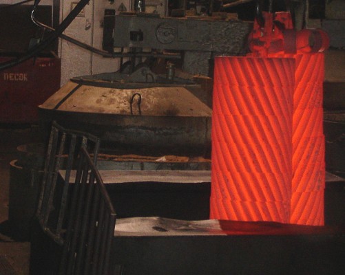
4 . Technological process of repair 4 .1 Analysis of possible defects The low gear may have the following defects: Wear of teeth in thickness and length; Broken teeth; Fatigue failure in the form of shells on the surface; Keyway wear 4 .2 Recoveryworn outx teeth by vibro-arc surfacing Materials used: wire NP-65G. Equipment: when restoring parts that have the shape of bodies of revolution, a lathe with a reduction gear is used. Part rotation speed n = 3 min-1. Deposition step t = 2 mm. Electrode wire feed speed v = 2m/min. Voltage 24 V. Current strength 180 A. Table 3 - Route for restoring worn teeth. Drilling a new keyway to replace a worn one Equipment: horizontal - broaching machine 7B510. Do they pull out the new keyway at an angle of 90 - 120? to the damaged one, and the old one is welded. 4.3 Restoration of worn teeth using plastic deformation methods The draft allows you to restore worn teeth up to 0.5 mm in thickness. It is carried out in dies under pressure with pre-heating of the parts. Equipment: The required pressure is calculated using the formula: Where? T is the yield strength of the gear material; ? T = 250 MPa. D - gear diameter; l - gear length. Table 4 - Route for restoring worn teeth. 4. 4 Restoration of worn gear surfaces by leaving Recovery options and modes: Metal deposition rate 0.4 mm/h Current efficiency 85% Current density 30 A/dm 2 The technological process of cooling includes the following operations: Cleaning the part from dirt and oil Mechanical restoration Flushing with gasoline Insulation of non-coated surfaces Remaining Hot water rinsing Neutralization Mechanical restoration Conclusion As a result of the work carried out, a technological process for manufacturing and repairing gears was developed. Based on the calculations of the course project, the following were chosen: the optimal method for obtaining a workpiece, which takes into account all existing recommendations that contribute to the lowest cost of manufacturing the part and the types of machines that are necessary for the production of parts in accordance with this option. Feed, cutting speed, spindle speed and main time are calculated for all types of machines. And the technological process of repair is given. In the process of work, practical skills were obtained in choosing the optimal variant of the manufacturing process, as well as the skills necessary in the field of design were acquired. List of sources used 1. Metal cutting modes. Handbook edited by Yu.V. Baranovsky. M.: Mechanical Engineering, 1972- 407 p. 2. General machine-building standards for cutting modes for technical regulation of work on metal-cutting machines. Part 1. M.: Mechanical Engineering, 1974.- 417 p. 3. General machine-building standards for cutting modes for technical regulation of work on metal-cutting machines. Part 2, M.: Mechanical Engineering, 1974.- 200 p. 4. Gorbatsevich A.F., Shkred V.A.. Course design in mechanical engineering technology: - 4th ed., revised. and additional - Mn.: Higher. School, 1983. - 256 p. 5. Guidelines for completing course work on machine repair. Mogilev. State University of Higher Professional Education Belarusian-Russian University, 2007 - 31 p. Posted on Allbest.ru Similar documentsPurpose of the part, material, mechanical properties, chemical composition. Analysis of manufacturability of part design. Assigning a route for processing individual surfaces. Analytical calculation of allowances for diametrical dimensions. Milling and drilling. course work, added 02/10/2009 Official appointment and technical specifications gears. Analysis of manufacturability of part design. Development of a technological process for processing a part. Calculation of allowances and processing accuracy. Design of equipment for the production of keyways. course work, added 11/16/2014 Description of the design of the gear and the conditions of its operation in the mechanism. Analysis of the manufacturability of the design and choice of method for obtaining the workpiece. Part processing route and determination of cutting modes. Analysis of possible defects and methods for quality restoration. course work, added 12/17/2013 Functional purpose and design of the part "Case 1445-27.004". Analysis of technical conditions for manufacturing parts. Choosing a method for obtaining a workpiece. Development of a technological route for processing a part. Calculation of processing allowances and cutting conditions. thesis, added 10/02/2014 The service purpose of the part, definition and justification of the type of production. Selection of general allowances, calculation of workpiece dimensions with tolerances, material utilization rate. Calculation of interoperational allowances. Description and principle of operation of the device. course work, added 01/03/2014 Description of the design and purpose of the “Pusher housing” part. Selection and calculation of workpieces. Lost wax casting in a mold. Calculation of the amount of equipment and its load. Development of a technological process, route for machining a part. course work, added 04/29/2012 Technology for manufacturing a gear blank, development and description of the design of the part; justification for choosing options. Determination of dimensions and deviations of the workpiece and allowances for machining; weight calculation, selection of equipment and accessories. course work, added 03/13/2012 Characteristics of the workpiece, workpiece material. Selection of the optimal method for obtaining the workpiece. Development of a technological route for processing a part. Centering workpieces on screw-cutting lathes. Calculation of devices for accuracy. test, added 12/04/2013 Choosing a method for obtaining the workpiece. Analysis of manufacturability of part design. Selection of workpiece surface treatment methods, workpiece basing schemes. Calculation of allowances, intermediate technological dimensions. Design of special equipment. course work, added 02/04/2014 Description of the design of the drive gear: purpose, operating conditions; manufacturing process plan. Justification for the choice of material, analysis of manufacturability. Selecting a method for obtaining a workpiece, calculating the number of surface processing steps. 1. Manufacturing of blanks (cutting, forging, stamping)The workpieces are cut from a circle (max Ø340 mm) on a band saw. - free forging or in backing dies on hammers. Heating of blanks for forging is carried out in gas furnaces of our own production. Loading and unloading is done manually.
- hot stamping on presses in open dies. Heating of blanks for stamping is carried out in a gas furnace. 2. Heat treatmentForgings and stampings of gears are subjected to annealing (heating and cooling in a furnace) or normalization (heating in a furnace and cooling in air). Shaft electric furnaces are used for these purposes. By monitoring the hardness of forgings and stampings, measured on a Brinell device, the quality of the heat treatment performed is judged. 3. Turning (preliminary)Preliminary (rough) processing of the part is carried out: trimming the ends, centering before drilling holes, drilling, reaming holes, turning (semi-finishing) external surfaces, boring internal surfaces. The operation is performed on a CNC lathe. The maximum processing diameter is 700 mm. The maximum length of the processed workpiece is 1500 mm.
4. Turning finishingThe final (finishing) processing of the main areas of the surface of the part is carried out. The operation is performed on a CNC lathe.
5. Drilling processing (technological holes, lightening holes, etc.)The operation is performed on a CNC vertical drilling machine. 6. Gear processingCylindrical gears (straight and helical): Number of teeth processed: 6-300 Module: up to 14 Gear wheels are cut using hobs on gear hobbing machines.
The maximum processing diameter is 1250 mm. Maximum length of cut wheel tooth: 560 mm - straight teeth 400 mm - helical with a tooth angle of 30˚ 310 mm - helical with a tooth angle of 45˚ Bevel gears with straight teeth: Number of teeth processed: 10-200 Module: up to 8 Processing diameter: up to 500 mm Maximum width of the ring gear: up to 90 mm Inner cone angle: 4-90˚ Planing of bevel gears is carried out with cutters on semi-automatic gear planing machines. Bevel gears with circular tooth: Number of teeth processed: 5-150 Module: up to 16 Largest pitch diameter of cut wheels: 800 mm Maximum width of ring gear: 125 mm Pitch angle: 5.5-84˚ The cutting of bevel gears with a circular tooth is carried out using cutting heads on semi-automatic gear cutting machines.
7. Metalworking (chamfering and deburring)The chamfers are removed and sharp edges are dulled. 8. Heat treatment (cementation, hardening, tempering, shot blasting)Gears, depending on the material, are subjected to improvement (hardening and high tempering) or carburization. All thermal operations are carried out in shaft electric furnaces using devices developed at the plant.
Gears made of case-hardened steel grades are subjected to gas carburization in shaft muffle electric furnaces with the supply of liquid carburizer (kerosene). The depth of the cementation layer is judged by witness samples undergoing cementation along with the gears. Gears, after carburization, undergo normalization or high tempering, quenching with cooling in oil and low tempering. After heat treatment, all gears are cleaned of scale in a shot blasting unit and undergo tooth hardness testing using Rockwell instruments using specially designed and manufactured prisms. 9. Grinding (holes, necks, ends)External and internal surfaces are ground on grinding machines to achieve the required accuracy and cleanliness. Longest grinding length: 750 mm Largest grinding diameter: Ø200 mm.
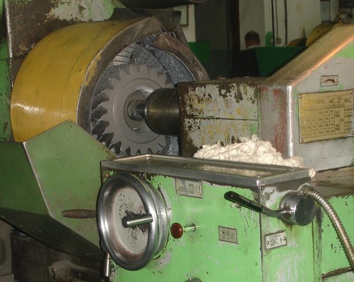
10. Broaching (keyway hole or slotted hole)The operation is performed on a horizontal broaching machine. 11. Gear grinding (cylindrical gears)The teeth of cylindrical gears are grinded using CNC semi-automatic gear grinding machines to achieve the required accuracy and cleanliness.
Maximum processing diameter: Ø800 mm Maximum length of grinded wheel tooth: 220 mm - straight teeth 212 mm - helical with a tooth angle of 15˚ 190 mm - helical with a tooth angle of 30˚ 155 mm - helical with a tooth angle of 45˚ 12. Final inspection of partsControl is carried out: Technological dimensions and surface roughness special. measurers, Tooth surfaces for microcracks in the UMD device, Surface run-out using: indicator ICH-02 class 1 GOST 577-68, run-out gauge B-10 TU-2-034-216-86, Deviation of the tooth profile on the KEU involute meter, Deviation of tooth direction on the UZP device - 400 13. Preservation and packagingGears undergo a preservation process in accordance with technical specifications and are packed in corrugated cardboard boxes or wooden boxes.
|
|||||||||||||||||||||||||||||||||||||||||||||||||||||||||||||||||||||||||||||||||||||||||||||||||||||||||||||||||||||||||||||||||||||||||||||||||||||||||||||||||||||||||||||||||||||||||||||||||||||||||||||||||||||||||||||||||||||||||||||||||||||||||||
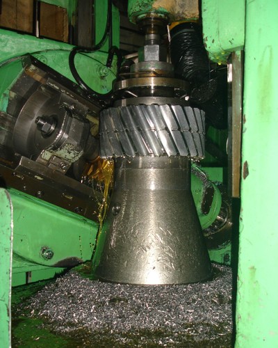
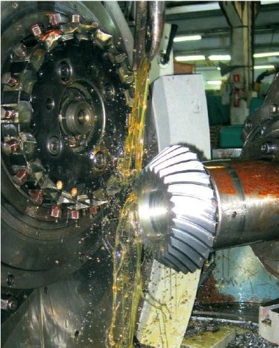
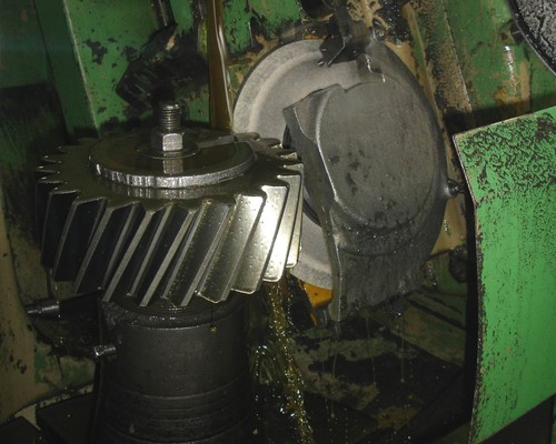
 This method allows you to produce a gear using a hob cutter. The cutting tool in this method is a hob cutter, which, together with the gear blank, produces a worm gear.
 One gear cavity is cut with a disk or finger cutter. The cutting part of the cutter, made in the shape of this cavity, cuts the gear. And with the assistance of the dividing device, the gear being cut is rotated by one angular step and the cutting process is repeated. This method of manufacturing gears was used at the beginning of the twentieth century, it is not accurate, the cavities of the produced gear are different, not identical.