
The size number is shown correctly in the picture.
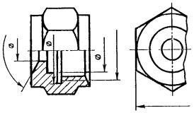
The size of the depicted part can only be determined by the dimensional numbers. They are applied above the dimension lines as close to their middle as possible (Fig. 21). Dimension lines are limited by arrows whose points touch extension lines, contour lines (see size ∅ 90 in Fig. 28, a) or center lines (see size ∅ 50 in Fig. 28, a).
The dimension line is drawn parallel to the segment, the size of which is indicated, if possible, outside the contour of the image. The distance between parallel dimension lines and from the dimension line to the outline of the image should be from 6 to 10 mm (the numbers are shown in the square in Fig. 21).
Dimension lines should not be allowed to intersect with extension lines or be a continuation of contour lines, axial, center and extension lines. It is prohibited to use contour lines, axial, center and extension lines as dimension lines.
Dimension lines cannot be crossed by extension lines, so the smaller size is applied closer to the image, and the larger one further away (sizes 20 and 35 and size 115 in Fig. 21).
The shape of the arrow is shown in Fig. 22. The sizes of the arrow elements of dimension lines are selected depending on the thickness of the lines of the visible contour. The size of the arrows should be kept approximately the same throughout the drawing.
Each size in the drawing is indicated only once.
Dimensional numbers of linear dimensions are applied in accordance with the position of the dimension lines, as shown in Fig. 23.
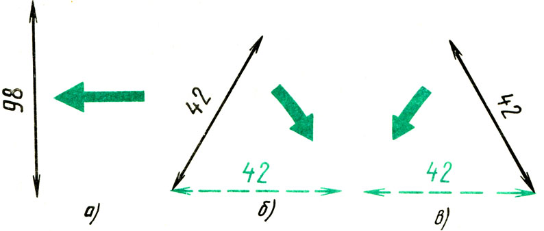
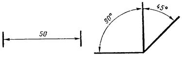
If the dimension line is vertical, then the dimension number is written and read on the right (Fig. 23, a). On inclined dimension lines, numbers are written so that they are in a normal readable position if the dimension line is allowed to “fall” to a horizontal position, as indicated by the arrows in Fig. 23, b and c.
Linear dimensions in the drawings are indicated in millimeters without indicating units of measurement (see dimensions 20, 35 R10, etc. in Fig. 21).
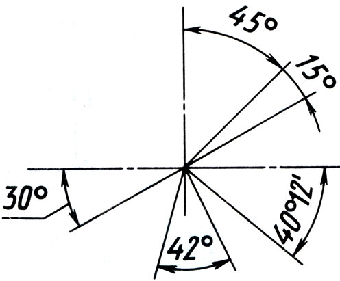
Angular dimensions are applied as shown in Fig. 21 and 24. They are indicated in degrees (°), minutes (") and seconds ("), putting down units of measurement, for example, size 40 ° 12 "in Fig. 24. The dimension line is drawn in the form of a circular arc with a center at top of the corner.
To indicate the diameter, the sign “∅” is applied in front of the dimension number in all cases - a circle crossed out by an inclined line. The use of this sign is shown in Fig. 25, and the construction is in Fig. 26, a.
To indicate the radius, the Latin capital letter R is always written in front of the dimension number (see Fig. 21 and 26, c). The radius dimension line is limited by an arrow on one side (from the arc side).
The dimensions of square elements are indicated with a sign, the outline of which is shown in Fig. 26, b. The flat surfaces of a square protrusion or hole are marked with thin intersecting lines (see Fig. 33, b).

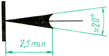
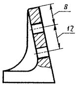
Many parts have chamfers - small conical surfaces (Fig. 27). If the chamfer is cut at an angle of 45°, then its size is recorded with a conventional inscription, the first number of which indicates the height of the chamfer, and the second - the size of the angle, for example, 5 x 45° (see Fig. 21 and 27, a). If the chamfer has an angle other than 45°, its size is indicated according to general rules, i.e. as shown in Fig. 27, b.

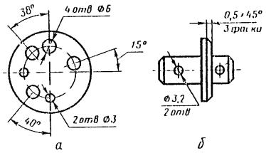
If a part has several identical holes, then it is recommended to mark the size of one of them, and indicate the hole number before the size number, for example, 4 holes. ∅ 16 (Fig. 28, a).
The dimensions of the thickness or length of a part represented by one type can be applied as shown in Fig. 28.
Before the number indicating the thickness of the part, put the letter c (Fig. 28, a), and before the number indicating the length of the part, put the letter l (Fig. 28, b).

If there is no space to write the dimensional number inside the circle, then it is taken outside the circle and applied using one of the methods shown in Fig. 29. Proceed similarly when applying the dimensions of radii and straight segments.

To avoid mistakes when reading sizes, you need to keep track of where the size line ends, referring to the number you name.
Please note how the dimensional numbers 15 ±0.1 and ∅ 50 -0.2 are written in Fig. 21. What do such entries mean? This is how maximum deviations from a given size are applied. Numbers ±0.1; -0.2 shows what inaccuracy in relation to the main (nominal) size can be allowed when manufacturing a part. For example, a size with maximum deviations of 40 +0.1 -0.2 should be understood as follows: the assigned main (nominal) size is 40 mm; it is allowed to manufacture a part 0.1 mm larger or 0.2 mm smaller than the size of 40 mm; therefore, to determine the largest maximum size, you need to add 0.1 to 40, and to calculate the smallest maximum size, you need to subtract 0.2 from 40. Thus, the maximum dimensions are calculated as follows:
40 + 0.1 = 40.1 mm (largest);
40 - 0.2 = 39.8 mm (smallest).
All parts whose actual size is 39.8 mm or more or 40.1 mm or less are valid.
If only one maximum deviation is indicated, for example, ∅ 50 +0.05, then the second deviation is equal to zero (in the drawings, deviations equal to zero are not indicated). Largest size limit in this case it will be 50 + 0.05 = 50.05 mm, the smallest is 50 mm. For size ∅ 50 -0.03, the maximum dimensions will be: 50 mm and 50 - 0.03 = 49.97 mm.
In Fig. Figure 30 shows how to arrange numerical values maximum deviations in relation to the nominal size. The height of the numbers indicating maximum deviations is usually less than the height of the numbers of the nominal size (Fig. 30, a-c). If the magnitude of the positive and negative deviations is the same, only one number with ± signs is written to the right of the nominal size, and the height of the numbers indicating the deviations should be the same as the height of the numbers indicating the nominal size (Fig. 30, d).

Answer the questions?
1. On what basis are the dimensions of the part shown in the drawing judged?
2. In what units are linear dimensions expressed in mechanical engineering drawings (if the unit of measurement is not indicated)?
3. How is the size number placed in relation to the size line?
4. What distance is left between the outline of the image and the dimension line? Between parallel dimension lines?
5. How to understand the ∅ sign placed in front of the dimensional number with
6. What does the R sign in front of the size number mean?
8. How to check the correctness of dimensional numbers on inclined dimensional lines?
9. How to understand the inscription: 3 x 45°?
10. What do numbers with a plus or minus sign mean, placed after the size number, for example 36 +0.2 -0.1?
Assignment for § 5
Exercise 17

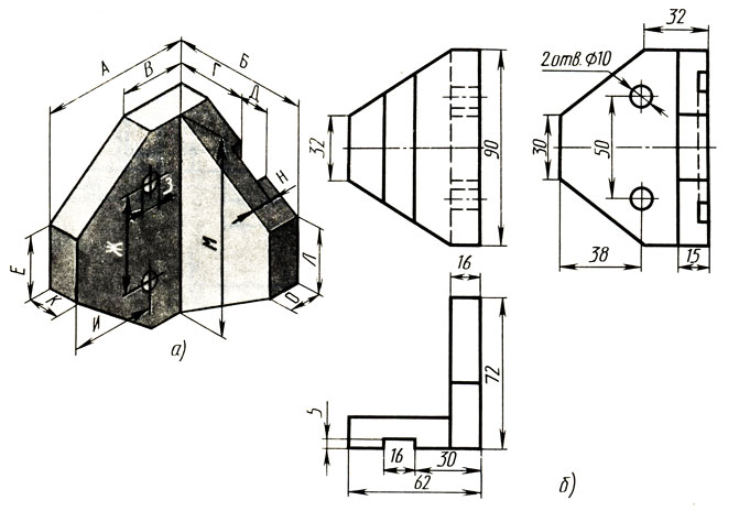
Write down in your notebook which letter size designations in the visual image (Fig. 31, a) correspond to the numerical sizes in the three views (Fig. 31, b). Position of the part in Fig. 31, a and b are given differently.

Exercise 18

Draw the figure in your notebook. 32, a and b. Apply on them the dimensions given in the visual images.

Exercise 19
Place transparent paper over the visual images (Fig. 33). Transfer the dimensions from the three types to visual images and write them down on transparent paper.

Exercise 20
In Fig. 34 and 35 give examples of correct and incorrect placement of dimension lines. Write down in your notebook which letters indicate the correct drawings. Identify the errors contained in the remaining drawings.


Exercise 21
Write down in your notebook which drawing shows the correct dimensional numbers (Fig. 36). What are the errors in the other drawings?

Exercise 22
Rice. 39. Parts drawingsExercise 25
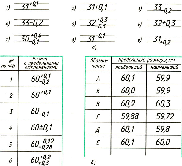
Write down in your notebook the numbers of examples (Fig. 40, a), in which the numerical values of the maximum deviations are correctly located in relation to the numbers indicating the nominal dimensions. What are the mistakes in the other examples? In Fig. 40, b on the left are the dimensions with maximum deviations. On the right are the numerical values of the maximum sizes, but in a different sequence. Calculate the maximum dimensions and fill out the following table in your notebook:

Exercise 26

Draw the figure in your notebook. 21 and 23 and those examples from Fig. 34, 38 and 39, which you chose as correct. Give appropriate captions for these drawings. At the beginning of your work, write the heading “Applying dimensions.” As a result, your notebook will contain a summary for repeating the material in the paragraph on sizes.
Exercise 27
Take the filmstrip “Applying Dimensions on Drawings” from the school’s film library and repeat the material on the topic.
DIMENSIONING
AND LIMIT DEVIATIONS
GOST 2.307-68
(ST SEV 1976-79, ST SEV 2180-80)
STATE STANDARD OF THE USSR UNION
|
Unified system of design documentation APPLICATION OF DIMENSIONS AND LIMIT DEVIATIONS Unified system for design documentation. |
GOST (ST SEV 1976-79, |
Date of introduction 01.01.71
This standard establishes the rules for drawing dimensions and maximum deviations on drawings and other technical documents for products from all sectors of industry and construction.
(Changed edition, Amendment No. 3).
1. BASIC REQUIREMENTS
The exception is the cases provided for in GOST 2.414-75; GOST 2.417-78; GOST 2.419-68, when the size of a product or its elements is determined from images made with a sufficient degree of accuracy.
The basis for determining the required accuracy of a product during manufacturing is the maximum dimensional deviations indicated in the drawing, as well as the maximum deviations of the shape and location of surfaces.
1.2. The total number of dimensions in the drawing should be minimal, but sufficient for the manufacture and control of the product.
1.3. Dimensions that cannot be made according to this drawing and are indicated for greater convenience in using the drawing are called reference.
1.4. Reference dimensions in the drawing are marked with a “*” sign, and in the technical requirements they write: “* Dimensions for reference.” If all the dimensions in the drawing are for reference, they are not marked with the “*” sign, but in the technical requirements they write: “Dimensions for reference.”
On construction drawings, reference dimensions are noted and specified only in cases provided for in the relevant documents approved in the prescribed manner.
a) one of the closed sizes dimensional chain. Maximum deviations of such dimensions are not indicated in the drawing (Fig.);
a) when indicating the size of the diameter of a circle, regardless of whether the circle is depicted completely or partially, while the break in the dimension line is made further than the center of the circle (Fig.);
A general record of maximum deviations of dimensions with unspecified tolerances must contain symbols of maximum deviations of linear dimensions in accordance with (for deviations by quality) or according to GOST 25670-83 (for deviations by accuracy classes). Symmetrical maximum deviations assigned according to qualifications should be designated indicating the qualification number.
Designations of one-sided maximum deviations according to qualifications assigned only for round holes and shafts (option 4 according to GOST 25670-83) are supplemented with a diameter sign (Æ ).
Examples of general records corresponding to options in accordance with GOST 25670-83 for grade 14 and (or) accuracy class “medium” are given in table. :
Table 1
|
Example of writing with symbols |
|
|
N 14, h 14, or N 14, h 14, |
|
|
+ t 2 , - t 2, |
|
|
Or |
|
|
Æ N 14, Æ h 14, orÆ N 14, Æ h 14, |
Date of introduction 01.01.71
This standard establishes the rules for drawing dimensions and maximum deviations on drawings and other technical documents for products from all sectors of industry and construction. (Changed edition, Amendment No. 3).
1. BASIC REQUIREMENTS
1.1. The basis for determining the size of the depicted product and its elements are the dimensional numbers printed on the drawing. The exception is the cases provided for in GOST 2.414-75; GOST 2.417-78; GOST 2.419-68, when the size of a product or its elements is determined from images made with a sufficient degree of accuracy. The basis for determining the required accuracy of a product during manufacturing is the maximum dimensional deviations indicated in the drawing, as well as the maximum deviations of the shape and location of surfaces. 1.2. The total number of dimensions in the drawing should be minimal, but sufficient for the manufacture and control of the product. 1.3. Dimensions that cannot be made according to this drawing and are indicated for greater convenience in using the drawing are called reference. 1.4. Reference dimensions in the drawing are marked with a “*” sign, and in the technical requirements they write: “* Dimensions for reference.” If all the dimensions in the drawing are for reference, they are not marked with the “*” sign, but in the technical requirements they write: “Dimensions for reference.” On construction drawings, reference dimensions are noted and specified only in cases provided for in the relevant documents approved in the prescribed manner. 1.5. The following dimensions are referenced: a) one of the dimensions of a closed dimensional chain. Maximum deviations of such dimensions are not indicated in the drawing (Fig. 1);
B) dimensions transferred from the drawings of blank products (Fig. 2);

C) dimensions that determine the position of the elements of the part to be processed on another part (Fig. 3);

D) dimensions on the assembly drawing, which determine the limiting positions of individual structural elements, for example, piston stroke, valve rod stroke of an internal combustion engine, etc.; e) dimensions on the assembly drawing, transferred from the drawings of parts and used as installation and connecting ones; f) overall dimensions on the assembly drawing, transferred from the drawings of parts or being the sum of the dimensions of several parts: g) dimensions of parts (elements) made of long, shaped, sheet and other rolled products, if they are fully determined by the designation of the material given in column 3 of the main inscription. Notes:1. The reference dimensions specified in subparagraphs b, c, d, f, g of this paragraph may be applied both with maximum deviations and without them2. Installation and connecting dimensions are dimensions that determine the dimensions of the elements by which this product is installed at the installation site or connected to another product.3. Dimensions are dimensions that determine the maximum external (or internal) outline of the product. 1.6. On the drawings of products in sizes that are technically difficult to control; put the “*” sign, and in the technical requirements the inscription “Provision dimensions” is placed. instr." Note. This inscription means that the execution of the size specified in the drawing with a maximum deviation must be guaranteed by the size of the tool or the corresponding technological process. In this case, the dimensions of the tool or the technological process are checked periodically during the manufacturing process of products. The frequency of monitoring of a tool or technological process is established by the manufacturer together with the customer’s representative. 1.7. It is not allowed to repeat the dimensions of the same element in different images, technical requirements, title block and specifications. The exception is the reference dimensions given in paragraph 1.5 b and g. If in the technical requirements it is necessary to give reference to the size marked on the image, then this size or the corresponding element is indicated by a letter, and in the technical requirements an entry similar to that shown in the drawing is placed. 4.
Dimensions may be repeated on construction drawings. 1.5-1.7. (Changed edition, Amendment No. 2). 1.8. Linear dimensions and their maximum deviations in drawings and specifications are indicated in millimeters, without indicating a unit of measurement. For dimensions and maximum deviations given in the technical requirements and explanatory notes on the drawing field, units of measurement must be indicated. (Changed edition, Amendment No. 3). 1.9. If the dimensions in the drawing must be indicated not in millimeters, but in other units of measurement (centimeters, meters, etc.), then the corresponding dimensional numbers are written down with the designation of the unit of measurement (cm, m) or indicated in the technical requirements. In these cases, units of measurement may not be indicated on construction drawings if they are specified in the relevant documents approved in the prescribed manner 1.10. Angular dimensions and maximum deviations of angular dimensions are indicated in degrees, minutes and seconds with the designation of the unit of measurement, for example - 4°; 4°30"; 12°45"30"; 0°30"40"; 0°18"; 0°5"25"; 0°0"30"; 30°±l°; 30°±10".


1.11. For dimensional numbers, simple fractions are not allowed, with the exception of sizes in inches. 1.12. The dimensions that determine the location of the mating surfaces are set, as a rule, from the structural bases, taking into account the possibilities of making and controlling these dimensions. 1.13. When the elements of an object (holes, grooves, teeth, etc.) are located on one axis or on one circle, the dimensions that determine their relative position are applied in the following ways: from a common base (surface, axis) - along the lines. 5a and b; specifying the sizes of several groups of elements from several common bases - according to the drawing. 5c; setting the dimensions between adjacent elements (chain) - according to the drawing. 6. 1.14. Dimensions on drawings are not allowed to be drawn in the form of a closed chain, except in cases where one of the dimensions is indicated as a reference (see Drawing 1). On construction drawings, dimensions are applied in the form of a closed circuit, except for cases provided for in the relevant documents approved in the prescribed manner. The dimensions that determine the position of symmetrically located surfaces of symmetrical products are applied as shown in Fig. 7 and 8.

(Changed edition, Amendment No. 2). 1.15. For all dimensions marked on the working drawings, maximum deviations are indicated. It is allowed not to indicate the maximum deviations: a) for dimensions defining zones of different roughness of the same surface, zones of heat treatment, coating, finishing, knurling, notches, as well as the diameters of knurled and notched surfaces. In these cases, the sign “” is applied directly to such dimensions; b) for the dimensions of parts of individually produced products specified with an allowance for fit. On such drawings, in the immediate vicinity of the indicated dimensions, the sign “*” is applied, and in the technical requirements they indicate: “* Dimensions with allowance for fit to detail. . . . . ", "* Dimensions with allowance for fit as shown. . . . . ", "* Dimensions with allowance for fit, according to the mating part." On construction drawings, maximum dimensional deviations are indicated only in cases provided for in the relevant documents approved in the prescribed manner. 1.16. When making working drawings of parts manufactured by casting, stamping, forging or rolling with subsequent machining of part of the surface of the part, indicate no more than one size in each coordinate direction, connecting the machined surfaces with surfaces not subject to machining (Fig. 9 and 10) .

(Changed edition, Amendment No. 2). 1.17. If an element is depicted at a deviation from the image scale, then the size number should be emphasized (Fig. 10a).

(Introduced additionally, Amendment No. 2).
2. DIMENSIONING
2.1. Dimensions in the drawings are indicated by dimensional numbers and dimension lines. 2.2. When applying the size of a straight segment, the dimension line is drawn parallel to this segment, and extension lines are drawn perpendicular to the dimension lines (Fig. 11).
2.3. When applying the size of an angle, the dimension line is drawn in the form of an arc with the center at its apex, and the extension lines are drawn radially (Fig. 12).

2.4. When applying the size of a circular arc, the dimension line is drawn concentrically to the arc, and the extension lines are parallel to the bisector of the angle, and the sign “Ç” is placed above the dimension number (Fig. 13).
It is allowed to place extension lines of the arc size radially, and if there are also concentric arcs, it is necessary to indicate which arc the size belongs to (Fig. 14).
2.4a. When drawing dimensions of parts similar to those shown in Fig. 14a, dimension lines should be drawn in the radial direction, and extension lines should be drawn along circular arcs (Fig. 14a).
![]()
(Introduced additionally, Amendment No. 2). 2.5. The dimension line at both ends is limited by arrows resting on the corresponding lines, except for the cases given in paragraphs. 2.16, 2.17, 2.20 and 2.21, and when drawing a radius line limited by an arrow on the side of the defined arc or fillet. In construction drawings, instead of arrows, it is allowed to use serifs at the intersection of dimension and extension lines, and the dimension lines must protrude beyond the outer extension lines by 1 . . . 3 mm. 2.6. In the cases shown in Fig. 15, the dimension and extension lines are drawn so that they, together with the measured segment, form a parallelogram.

2.7. It is allowed to draw dimension lines directly to the lines of the visible contour, axial, center and other lines (Fig. 16 and 17).

2.8. It is preferable to apply dimension lines outside the outline of the image. 2.9. Extension lines should extend beyond the ends of the dimension line arrows by 1. . 5 mm. 2.10. The minimum distances between parallel dimension lines should be 7 mm, and between the dimension and contour lines - 10 mm and are selected depending on the size of the image and the saturation of the drawing. (Changed edition, Amendment No. 2). 2.11. It is necessary to avoid intersections of dimension and extension lines (see Figure 16). 2.12. It is not allowed to use contour lines, axial, center and extension lines as dimension lines. 2.13. Extension lines are drawn from the lines of the visible contour, except for the cases specified in paragraphs. 2.14 and 2.15, and cases when, when drawing dimensions on an invisible contour, there is no need to draw an additional image. 2.14. The contour dimensions of the curved profile are applied as shown in Fig. 16 and 17. 2.15. If you need to show the coordinates of the vertex of the corner being rounded or the center of the rounding arc, then extension lines are drawn from the point of intersection of the sides of the corner being rounded or the center of the rounding arc (Fig. 18).

2.16. If a view or section of a symmetrical object or individual symmetrically located elements is depicted only up to the axis of symmetry or with a break, then the dimension lines related to these elements are drawn with a break, and the break of the dimension line is made further than the axis or break line of the object (Fig. 19).
In construction drawings in such cases, all dimensions may be indicated only up to the axis of symmetry, and the dimension lines at the intersection with the axis of symmetry may be limited by a serif cross. 2.17. Dimension lines may be drawn with a break in the following cases: a) when indicating the size of the diameter of a circle, regardless of whether the circle is depicted in whole or in part, while the break of the dimension line is made further than the center of the circle (Fig. 20);

B) when drawing dimensions from a base not shown in this drawing (Fig. 21).
2.18. When depicting a product with a gap, the dimension line is not interrupted (Fig. 22).

2.19. The values of the elements of the dimension line arrows are selected depending on the thickness of the lines of the visible contour and they are drawn approximately the same throughout the entire drawing. The shape of the arrow and the approximate relationship of its elements are shown in Fig. 23.

(Changed edition, Amendment No. 2). 2.20. If the length of the dimension line is not sufficient to place arrows on it, then the dimension line is continued beyond the extension lines (or, accordingly, beyond the contour, axial, center, etc.) and the arrows are drawn as shown in Fig. 24.

2.21. If there is not enough space for arrows on dimension lines arranged in a chain, the arrows can be replaced with serifs applied at an angle of 45° to the dimension lines (Fig. 25), or clearly marked dots (Fig. 26).


2.22. If there is not enough space for the arrow due to a closely located contour or extension line, the latter can be interrupted (Fig. 24 and 27).

2.23. Dimensional numbers are applied above the dimension line, as close as possible to its middle (Fig. 28).
2.24. When applying a diameter size inside a circle, the dimensional numbers are shifted relative to the middle of the dimensional lines. 2.25. When drawing several parallel or concentric dimension lines at a short distance from each other, it is recommended to place the dimension numbers above them in a checkerboard pattern (Fig. 29).

2.26. Dimensional numbers of linear dimensions with different inclinations of dimension lines are placed as shown in figure 30.
If it is necessary to apply a dimension in the shaded area, the corresponding dimension number is marked on the shelf of the leader line (Fig. 31).
2.27. Angular dimensions are applied as shown in Fig. 32. In the area located above the horizontal center line, dimensional numbers are placed above the dimensional lines on the side of their convexity; in the area located below the horizontal center line - from the side of the concavity of the dimension lines. It is not recommended to apply dimensional numbers in the shaded area. In this case, the dimensional numbers are indicated on horizontally applied shelves.

For small corners with a lack of space, dimensional numbers are placed on the shelves of leader lines in any zone (Fig. 33).

2.28. On construction drawings, it is allowed to apply linear and angular dimensional numbers and inscriptions without shelves of leader lines. 2.29. If there is not enough space above the dimension line to write the size number, then the dimensions are applied as shown in Fig. 34; if there is not enough space to apply the arrows, then they are applied as shown in the diagram. 35.


The method of applying the dimensional number at different positions of the dimensional lines (arrows) in the drawing is determined by the greatest ease of reading. 2.30. Dimensional numbers and maximum deviations are not allowed to be divided or crossed by any drawing lines. It is not allowed to break the contour line to apply the dimensional number and apply dimensional numbers at the intersection of dimensional, center or center lines. At the place where the dimension number is applied, the axial, center and hatch lines are interrupted (Fig. 36 and 37).


2.29, 2.30. (Changed edition, Amendment No. 2). 2.31. It is recommended to group dimensions related to the same structural element (groove, protrusion, hole, etc.) in one place, placing them in the image in which the geometric shape of this element is shown most fully (Fig. 38).
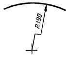
2.32. When applying a radius size, place a capital letter R in front of the size number. 2.33. If, when drawing the size of the radius of an arc of a circle, it is necessary to indicate the size that determines the position of its center, then the latter is depicted as the intersection of center or extension lines. If the radius is large, the center can be brought closer to the arc; in this case, the radius dimension line is shown with a bend at an angle of 90 ° (Fig. 39).
2.34. If it is not necessary to indicate the dimensions that determine the position of the center of the circular arc, then the radius dimension line may not be brought to the center and may be shifted relative to the center (Fig. 40).
2.35. When drawing several radii from one center, the dimension lines of any two radii are not placed on the same straight line (Fig. 41).

If the centers of several radii coincide, their dimension lines may not be brought to the center, except for the extreme ones (Fig. 41a).
2.36. The dimensions of the outer rounding radii are applied as shown in Fig. 42, internal roundings - to hell. 43.
![]()

Rounding radii, the size of which on the drawing scale is 1 mm or less, are not shown in the drawing and their dimensions are indicated as shown in Fig. 43a.
The method of applying dimensional numbers at different positions of dimensional lines (arrows) in the drawing is determined by the greatest ease of reading. Dimensions of identical radii may be indicated on a common shelf, as shown in Fig. 43b:

If the radii of fillets, bends, etc. are the same throughout the entire drawing or one radius is predominant, then instead of plotting the dimensions of these radii directly on the image, it is recommended to make an entry in the technical requirements like: “Fillet radii 4 mm”; “Internal bend radii 10 mm”; “Unspecified radii 8 mm”, etc. 2.35, 2.36. (Changed edition, Amendment No. 2). 2.37. When indicating the diameter size (in all cases), the sign “Æ” is placed before the size number. 2.38. Before the dimensional number of the diameter (radius) of the sphere, the sign Æ (R) is also applied without the inscription “Sphere” (Fig. 44). If it is difficult to distinguish a sphere from other surfaces in a drawing, then the word “Sphere” or the sign O can be written before the dimension number of the diameter (radius), for example, “Sphere Æ 18, OR12”. The diameter of the sphere sign is equal to the size of the dimensional numbers in the drawing.
2.39. The dimensions of the square are applied as shown in Fig. 45, 46 and 46a.
![]()

The height of the □ sign must be equal to the height of the dimensional numbers on the drawing. 2.38, 2.39 (Changed edition, Amendment No. 2). 2.40. Before the dimensional number characterizing the taper, the sign “< », острый угол которого должен быть направлен в сторону вершины конуса (черт. 47).

The cone sign and taper as a ratio should be marked above the center line or on the shelf of the leader line. 2.41. The surface slope should be indicated directly next to the image of the slope surface or on the shelf of the leader line in the form of a ratio (Fig. 48a), as a percentage (Fig. 48b) or in ppm (Fig. 48c). Before the dimensional number that determines the slope, the sign “< », острый угол которого должен быть направлен в сторону уклона.

2.42. Markings of levels (height, depth) of a structure or its element from any reference level, taken as “zero” in the view and section, are placed on extension lines (or on contour lines) and are indicated by the sign “¯” made by solid thin lines, the length of the strokes is 2 - 4 mm at an angle of 45° to the extension line or contour line (Fig. 49a), in the top view they should be applied in a frame directly on the image or on the leader line (Fig. 49b), or as shown in Fig. 49a.

Level marks are indicated in meters accurate to the third decimal place without indicating the unit of measurement. 2.43. The dimensions of the chamfers at an angle of 45° are applied as shown in Fig. 50.

It is allowed to indicate the dimensions of a chamfer not shown in the drawing at an angle of 45°, the size of which in the drawing scale is 1 mm or less, on the shelf of a leader line drawn from the edge (Fig. 50a).
The dimensions of chamfers at other angles are indicated according to the general rules - linear and angular dimensions (Fig. 51a and b) or two linear dimensions (Fig. 51c).

2.40-2.43. (Changed edition, Amendment No. 2). 2.44. The dimensions of several identical elements of the product, as a rule, are applied once, indicating the number of these elements on the shelf with a leader line (Fig. 52a). It is allowed to indicate the number of elements, as shown in Fig. 52b.
2.45. When applying the dimensions of elements evenly spaced around the circumference of the product (for example, holes), instead of the angular dimensions that determine the relative position of the elements, only their number is indicated (Fig. 53-55).

2.46. The dimensions of two symmetrically located elements of the product (except for holes) are applied once without indicating their number, grouping, as a rule, all dimensions in one place (Fig. 56 and 57).


The number of identical holes is always indicated in full, and their dimensions are indicated only once. (Changed edition, Amendment No. 2). 2.47. When applying dimensions that determine the distance between evenly spaced identical elements of a product (for example, holes), it is recommended, instead of dimensional chains, to apply the size between adjacent elements and the size between extreme elements in the form of the product of the number of spaces between the elements and the size of the gap (Fig. 58).
2.47a. It is allowed not to indicate on the drawing the dimensions of the radius of the arc of a circle of mating parallel lines (Fig. 58a).
(Introduced additionally, Amendment No. 2). 2.48. With a large number of dimensions applied from a common base, it is allowed to apply linear and angular dimensions, as shown in Fig. 59 and 60, while drawing a common dimension line from the mark “0” and dimension numbers are applied in the direction of the extension lines at their ends.

2.48a. The dimensions of the diameters of a cylindrical product of complex configuration can be applied as shown in Fig. 60a.
(Introduced additionally, Amendment No. 2). 2.49. If there are a large number of similar elements of the product, unevenly located on the surface, it is allowed to indicate their dimensions in a summary table, using the coordinate method of drawing holes with their designation in Arabic numerals (Fig. 61), or designating similar elements in capital letters (Fig. 61a).

|
Hole designation |
Size, mm |
2.51. If identical elements of the product (for example, holes) are located on different surfaces and are shown in different images, then the number of these elements is recorded separately for each surface (Fig. 63).

It is allowed to repeat the dimensions of identical elements of a product or their groups (including holes) lying on the same surface only if they are significantly removed from each other and are not related to each other in size (Fig. 64 and 65).

2.49-2.51. (Changed edition, Amendment No. 2). 2.52. If the drawing shows several groups of holes of similar sizes, it is recommended to mark the same holes with one of the symbols shown in the drawing. 66. It is allowed to use other symbols.
The holes are indicated by symbols in the image, which shows the dimensions that determine the position of these holes. On construction drawings, it is allowed to outline identical groups of holes with a solid thin line with an explanatory inscription. 2.53 When designating identical holes with conventional signs, the number of holes and their sizes may be indicated in the table (Figure 67).

(Changed edition, Amendment No. 2). 2.54. When depicting a part in one projection, the size of its thickness or length is applied as shown in Fig. 68.

2.55. The dimensions of a rectangular part or hole can be indicated on the leader line shelf by the dimensions of the sides through the multiplication sign. In this case, the size of the side of the rectangle from which the leader line is drawn should be indicated in the first place (Fig. 68a).

(Changed edition, Amendment No. 2).
3. APPLICATION OF LIMITED DIMENSIONS
3.1. Maximum dimensional deviations should be indicated immediately after the nominal dimensions. Maximum deviations of linear and angular dimensions of relatively low accuracy may not be indicated directly after the nominal dimensions, but may be specified by a general entry in the technical requirements of the drawing, provided that this entry unambiguously defines the values and signs of the maximum deviations. A general record of maximum deviations of dimensions with unspecified tolerances must contain symbols of maximum deviations of linear dimensions in accordance with GOST 25346-89 (for deviations by qualifications) or in accordance with GOST 25670-83 (for deviations by accuracy classes). Symmetrical maximum deviations assigned according to qualifications should be indicated by indicating the qualification number. Designations of one-sided maximum deviations according to qualifications assigned only for round holes and shafts (option 4 according to GOST 25670-83) are supplemented with a diameter sign (Æ). Examples of general records corresponding to options in accordance with GOST 25670-83 for grade 14 and (or) accuracy class “medium” are given in table. 1:Table 1
|
Option number |
Example of writing with symbols |
H14, h14, or H14, h14, | + t 2 , - t 2 , | or | ÆH14, Æ h14, or ÆH14, Æ h14, |
table 2
When indicating nominal dimensions with letter designations, tolerance fields must be indicated after a dash, for example, D -H 11. 3.3. When indicating maximum deviations with symbols, it is also necessary to indicate their numerical values in the following cases: a) when assigning maximum deviations (established by standards for tolerances and fits) of sizes not included in the series of normal linear dimensions according to GOST 6636-69, for example: 41.5 18N7 (+0.025), b) when assigning maximum deviations, the symbols of which are not provided in GOST 25347-82, for example, for a plastic part with maximum deviations in accordance with GOST 25349-88 (Fig. 69);
B) when assigning maximum deviations of the dimensions of ledges with an asymmetrical tolerance field (Fig. 70, 71);


D) (Deleted, Amendment No. 2). 3.4. Maximum deviations of angular dimensions are indicated only by numerical values (Fig. 72).
3.5. When recording maximum deviations in numerical values, the upper deviations are placed above the lower ones. Maximum deviations equal to zero are not indicated, for example: ; ; 60 +0.19; 60 -0.19. With a symmetrical arrangement of the tolerance field absolute value deviations are indicated once with the ± sign, and the height of the numbers defining the deviations must be equal to the height of the font of the nominal size, for example: 60 ± 0.23. 3.6. Maximum deviations, indicated by numerical values expressed as a decimal fraction, are written down to the last significant digit inclusive, equalizing the number of digits in the upper and lower deviations by adding zeros, for example: ; 3.7. The maximum deviations of the dimensions of the parts shown in the assembled drawing are indicated in one of the following ways: a) in the form of a fraction, the numerator of which indicates symbol hole tolerance fields, and in the denominator - the symbol of the shaft tolerance field, for example: 50 or 50Н11/ h 11 (Fig. 73a); b) in the form of a fraction, the numerator of which indicates the numerical values of the maximum deviations of the hole, and the denominator - the numerical values of the maximum deviations of the shaft (Fig. 73b);

B 1) in the form of a fraction, in the numerator of which the symbol of the tolerance field of the hole is indicated, with its numerical value indicated on the right in parentheses, and in the denominator - the symbol of the tolerance field of the shaft, with its numerical value indicated on the right in parentheses (Fig. 73c); c) in the form of a record in which the maximum deviations of only one of the mating parts are indicated. In this case, it is necessary to explain which part these deviations relate to (Fig. 74).
3.8. When for surface areas with one nominal size different maximum deviations are assigned, the boundary between them is drawn with a solid thin line, and the nominal size is indicated with the corresponding maximum deviations for each section separately (Fig. 75).
The boundary line between areas should not be drawn through the shaded part of the image (Fig. 75a).

3.2-3.8. (Changed edition, Amendment No. 2). 3.9. If it is necessary to limit fluctuations in the size of identical elements of one part within part of the tolerance field (Fig. 76a) or it is necessary to limit the amount of accumulated error in the distance between repeating elements (Fig. 76b), then these data are indicated in the technical requirements.
3.10. When it is necessary to indicate only one limiting size (the second is limited in the direction of increase or decrease by some condition), after the size number indicate max or min, respectively (Fig. 77). It is also possible to indicate maximum dimensions on assembly drawings for gaps, interference, backlash, etc., for example: “The axial displacement of the cam must be maintained within 0.6-1.4 mm.”

3.11. Maximum deviations of the location of the hole axes can be specified in two ways: a) positional tolerances of the hole axes in accordance with the requirements of GOST 2.308-79; b) maximum deviations of dimensions coordinating the axes (Fig. 78 - 80).


1. Limit deviations of dimensions between the axes of any two holes. ±0.35 mm.2. The displacement of the axes from plane A is no more than 0.18 mm
Maximum deviations of dimensions diagonally between the axes of any two holes. ±0.5 mm.
If the tolerances for the location of the axes are dependent, then after the maximum deviations of the dimensions coordinating the axes, the sign of the dependent tolerance M should be indicated (Changed edition, Amendment No. 2).
INFORMATION DATA
1. DEVELOPED AND INTRODUCED by the Committee of Standards, Measures and Measuring Instruments under the Council of Ministers of the USSR EXECUTORS V. R. Verchenko, Yu. I. Stepanov, Ya. G. Starozhilets, B. Ya. Kabakov, L. V. Matveev, P. N Kolkin, V. N. Vzorov, M. G. Aranovsky, E. M. Koliseeva. 2. APPROVED AND ENTERED INTO EFFECT by the Decree of the Committee of Standards, Measures and Measuring Instruments under the Council of Ministers of the USSR in December 1967. 3. The standard fully complies with ST CMEA 1976-79 and ST CMEA 2180-80. 4. INSTEAD OF GOST 3458-59, GOST 9171-59, GOST 5292-60 regarding section. III 5. REFERENCED REGULATIVE AND TECHNICAL DOCUMENTS 6. REISSUE (December 1990) with Amendments 2, 3, approved in June 1983; Fast. 2650 dated June 22, 1983, September 1987 (IUS 9-83, 12-87).
is a quadrangular rectangle, which is a figure with equal angles and sides to each other. Word " square" comes from the Greek word " quadratus", which translated means - " quadrangular».
In technical drawings It is not uncommon to see parts or parts thereof that have a square cross-section. To reduce the total number of dimension lines in the drawing, in this case, a special sign “ ” is used, which means that this size is one of the sides of the square, and the size is indicated only here. The height of the sign is selected according to the height of the dimensional numbers.

Designation of a square section of a product
Parts areas, having a square cross-section, can often be found on the fastening elements of auxiliary and cutting tools. Installation bolts, used in this case, take on significant mechanical impacts at intervals determined by the technological process.
Machine vice, intended for installation on metal-cutting machines, are equipped with a power screw, at one end of which there is a square cross-section. This was done so that the cap handle, which accordingly has a hole with a square cross-section, can be freely removed and put on, and it becomes possible to change its angular position. The load applied to the vice mechanisms is also quite significant.
As you know, a significant part of rotating parts is manufactured on turning machines. In order to clamp a part or workpiece for subsequent machining, special self-centering chucks are used. The most common of them are three-jaw chucks, but there are also four-jaw chucks in which, by the way, you can clamp square parts or blanks from the corresponding rolled products. The square can also be clamped in two jaw chucks, and, as in four jaw chucks, the movement of the jaws, depending on the type, can be carried out independently or using a special mechanism based on “ Archimedean spiral", which allows you to move the clamping elements synchronously. There are even six-jaw chucks, all of them are united by the fact that to clamp the part, a key with a square head is used.
The design of a traditional type faucet includes a water supply control element, such as a rod. At one end of the rod there is a square section onto which a handle with a square hole is installed. The efforts here are not too great, but, nevertheless, the use of a hexagon is not appropriate here (during operation, the angles between the edges may simply collapse).
Square holes, unlike round holes, are the most labor-intensive to manufacture. Usually they are milled, drawn, special firmware is used, accelerated on a slotting machine, etc. Technologies such as - laser cutting or electrical discharge machining, allow hollow elements of this type to be processed more or less quickly.
There is, however, another, exotic way. It's about about drilling using a special tool. This method is based on the trajectory of movement " Reuleaux triangle", named after the German inventor and mechanical engineer Franz Relo, who lived in the nineteenth and early twentieth centuries, who was a long-time lecturer at the Berlin Royal Academy of Technology and eventually became its president. The cross-section of the drill is similar to the so-called " Reuleaux triangle", the sides of which are not straight segments, like a regular one, but arcs of the same size and radius. If, during the drilling process, using a special device, you move the axis of this tool along a special path, you will end up with a square hole with slightly rounded corners.
Date of introduction 01.01.71
This standard establishes the rules for drawing dimensions and maximum deviations on drawings and other technical documents for products from all sectors of industry and construction. (Changed edition, Amendment No. 3).
1. BASIC REQUIREMENTS
1.1. The basis for determining the size of the depicted product and its elements are the dimensional numbers printed on the drawing. The exception is the cases provided for in GOST 2.414-75; GOST 2.417-78; GOST 2.419-68, when the size of a product or its elements is determined from images made with a sufficient degree of accuracy. The basis for determining the required accuracy of a product during manufacturing is the maximum dimensional deviations indicated in the drawing, as well as the maximum deviations of the shape and location of surfaces. 1.2. The total number of dimensions in the drawing should be minimal, but sufficient for the manufacture and control of the product. 1.3. Dimensions that cannot be made according to this drawing and are indicated for greater convenience in using the drawing are called reference. 1.4. Reference dimensions in the drawing are marked with a “*” sign, and in the technical requirements they write: “* Dimensions for reference.” If all the dimensions in the drawing are for reference, they are not marked with the “*” sign, but in the technical requirements they write: “Dimensions for reference.” On construction drawings, reference dimensions are noted and specified only in cases provided for in the relevant documents approved in the prescribed manner. 1.5. The following dimensions are referenced: a) one of the dimensions of a closed dimensional chain. Maximum deviations of such dimensions are not indicated in the drawing (Fig. 1);
B) dimensions transferred from the drawings of blank products (Fig. 2);
C) dimensions that determine the position of the elements of the part to be processed on another part (Fig. 3);
D) dimensions on the assembly drawing, which determine the limiting positions of individual structural elements, for example, piston stroke, valve rod stroke of an internal combustion engine, etc.; e) dimensions on the assembly drawing, transferred from the drawings of parts and used as installation and connecting ones; f) overall dimensions on the assembly drawing, transferred from the drawings of parts or being the sum of the dimensions of several parts: g) dimensions of parts (elements) made of long, shaped, sheet and other rolled products, if they are fully determined by the designation of the material given in column 3 of the main inscription. Notes:1. The reference dimensions specified in subparagraphs b, c, d, f, g of this paragraph may be applied both with maximum deviations and without them2. Installation and connecting dimensions are dimensions that determine the dimensions of the elements by which this product is installed at the installation site or connected to another product.3. Dimensions are dimensions that determine the maximum external (or internal) outline of the product. 1.6. On the drawings of products in sizes that are technically difficult to control; put the “*” sign, and in the technical requirements the inscription “Provision dimensions” is placed. instr." Note. This inscription means that the execution of the size specified in the drawing with a maximum deviation must be guaranteed by the size of the tool or the corresponding technological process. In this case, the dimensions of the tool or the technological process are checked periodically during the manufacturing process of products. The frequency of monitoring of a tool or technological process is established by the manufacturer together with the customer’s representative. 1.7. It is not allowed to repeat the dimensions of the same element in different images, technical requirements, title block and specifications. The exception is the reference dimensions given in paragraph 1.5 b and g. If in the technical requirements it is necessary to give reference to the size marked on the image, then this size or the corresponding element is indicated by a letter, and in the technical requirements an entry similar to that shown in the drawing is placed. 4.
Dimensions may be repeated on construction drawings. 1.5-1.7. (Changed edition, Amendment No. 2). 1.8. Linear dimensions and their maximum deviations in drawings and specifications are indicated in millimeters, without indicating a unit of measurement. For dimensions and maximum deviations given in the technical requirements and explanatory notes on the drawing field, units of measurement must be indicated. (Changed edition, Amendment No. 3). 1.9. If the dimensions in the drawing must be indicated not in millimeters, but in other units of measurement (centimeters, meters, etc.), then the corresponding dimensional numbers are written down with the designation of the unit of measurement (cm, m) or indicated in the technical requirements. In these cases, units of measurement may not be indicated on construction drawings if they are specified in the relevant documents approved in the prescribed manner 1.10. Angular dimensions and maximum deviations of angular dimensions are indicated in degrees, minutes and seconds with the designation of the unit of measurement, for example - 4°; 4°30"; 12°45"30"; 0°30"40"; 0°18"; 0°5"25"; 0°0"30"; 30°±l°; 30°±10".
1.11. For dimensional numbers, simple fractions are not allowed, with the exception of sizes in inches. 1.12. The dimensions that determine the location of the mating surfaces are set, as a rule, from the structural bases, taking into account the possibilities of making and controlling these dimensions. 1.13. When the elements of an object (holes, grooves, teeth, etc.) are located on one axis or on one circle, the dimensions that determine their relative position are applied in the following ways: from a common base (surface, axis) - along the lines. 5a and b; specifying the sizes of several groups of elements from several common bases - according to the drawing. 5c; setting the dimensions between adjacent elements (chain) - according to the drawing. 6. 1.14. Dimensions on drawings are not allowed to be drawn in the form of a closed chain, except in cases where one of the dimensions is indicated as a reference (see Drawing 1). On construction drawings, dimensions are applied in the form of a closed circuit, except for cases provided for in the relevant documents approved in the prescribed manner. The dimensions that determine the position of symmetrically located surfaces of symmetrical products are applied as shown in Fig. 7 and 8.
(Changed edition, Amendment No. 2). 1.15. For all dimensions marked on the working drawings, maximum deviations are indicated. It is allowed not to indicate the maximum deviations: a) for dimensions defining zones of different roughness of the same surface, zones of heat treatment, coating, finishing, knurling, notches, as well as the diameters of knurled and notched surfaces. In these cases, the sign “” is applied directly to such dimensions; b) for the dimensions of parts of individually produced products specified with an allowance for fit. On such drawings, in the immediate vicinity of the indicated dimensions, the sign “*” is applied, and in the technical requirements they indicate: “* Dimensions with allowance for fit to detail. . . . . ", "* Dimensions with allowance for fit as shown. . . . . ", "* Dimensions with allowance for fit, according to the mating part." On construction drawings, maximum dimensional deviations are indicated only in cases provided for in the relevant documents approved in the prescribed manner. 1.16. When making working drawings of parts manufactured by casting, stamping, forging or rolling with subsequent machining of part of the surface of the part, indicate no more than one size in each coordinate direction, connecting the machined surfaces with surfaces not subject to machining (Fig. 9 and 10) .
(Changed edition, Amendment No. 2). 1.17. If an element is depicted at a deviation from the image scale, then the size number should be emphasized (Fig. 10a).
(Introduced additionally, Amendment No. 2).
2. DIMENSIONING
2.1. Dimensions in the drawings are indicated by dimensional numbers and dimension lines. 2.2. When applying the size of a straight segment, the dimension line is drawn parallel to this segment, and extension lines are drawn perpendicular to the dimension lines (Fig. 11).
2.3. When applying the size of an angle, the dimension line is drawn in the form of an arc with the center at its apex, and the extension lines are drawn radially (Fig. 12).
2.4. When applying the size of a circular arc, the dimension line is drawn concentrically to the arc, and the extension lines are parallel to the bisector of the angle, and the sign “Ç” is placed above the dimension number (Fig. 13).
It is allowed to place extension lines of the arc size radially, and if there are also concentric arcs, it is necessary to indicate which arc the size belongs to (Fig. 14).
2.4a. When drawing dimensions of parts similar to those shown in Fig. 14a, dimension lines should be drawn in the radial direction, and extension lines should be drawn along circular arcs (Fig. 14a).
![]()
(Introduced additionally, Amendment No. 2). 2.5. The dimension line at both ends is limited by arrows resting on the corresponding lines, except for the cases given in paragraphs. 2.16, 2.17, 2.20 and 2.21, and when drawing a radius line limited by an arrow on the side of the defined arc or fillet. In construction drawings, instead of arrows, it is allowed to use serifs at the intersection of dimension and extension lines, and the dimension lines must protrude beyond the outer extension lines by 1 . . . 3 mm. 2.6. In the cases shown in Fig. 15, the dimension and extension lines are drawn so that they, together with the measured segment, form a parallelogram.
2.7. It is allowed to draw dimension lines directly to the lines of the visible contour, axial, center and other lines (Fig. 16 and 17).
2.8. It is preferable to apply dimension lines outside the outline of the image. 2.9. Extension lines should extend beyond the ends of the dimension line arrows by 1. . 5 mm. 2.10. The minimum distances between parallel dimension lines should be 7 mm, and between the dimension and contour lines - 10 mm and are selected depending on the size of the image and the saturation of the drawing. (Changed edition, Amendment No. 2). 2.11. It is necessary to avoid intersections of dimension and extension lines (see Figure 16). 2.12. It is not allowed to use contour lines, axial, center and extension lines as dimension lines. 2.13. Extension lines are drawn from the lines of the visible contour, except for the cases specified in paragraphs. 2.14 and 2.15, and cases when, when drawing dimensions on an invisible contour, there is no need to draw an additional image. 2.14. The contour dimensions of the curved profile are applied as shown in Fig. 16 and 17. 2.15. If you need to show the coordinates of the vertex of the corner being rounded or the center of the rounding arc, then extension lines are drawn from the point of intersection of the sides of the corner being rounded or the center of the rounding arc (Fig. 18).
2.16. If a view or section of a symmetrical object or individual symmetrically located elements is depicted only up to the axis of symmetry or with a break, then the dimension lines related to these elements are drawn with a break, and the break of the dimension line is made further than the axis or break line of the object (Fig. 19).
In construction drawings in such cases, all dimensions may be indicated only up to the axis of symmetry, and the dimension lines at the intersection with the axis of symmetry may be limited by a serif cross. 2.17. Dimension lines may be drawn with a break in the following cases: a) when indicating the size of the diameter of a circle, regardless of whether the circle is depicted in whole or in part, while the break of the dimension line is made further than the center of the circle (Fig. 20);
B) when drawing dimensions from a base not shown in this drawing (Fig. 21).
2.18. When depicting a product with a gap, the dimension line is not interrupted (Fig. 22).
2.19. The values of the elements of the dimension line arrows are selected depending on the thickness of the lines of the visible contour and they are drawn approximately the same throughout the entire drawing. The shape of the arrow and the approximate relationship of its elements are shown in Fig. 23.
(Changed edition, Amendment No. 2). 2.20. If the length of the dimension line is not sufficient to place arrows on it, then the dimension line is continued beyond the extension lines (or, accordingly, beyond the contour, axial, center, etc.) and the arrows are drawn as shown in Fig. 24.
2.21. If there is not enough space for arrows on dimension lines arranged in a chain, the arrows can be replaced with serifs applied at an angle of 45° to the dimension lines (Fig. 25), or clearly marked dots (Fig. 26).
2.22. If there is not enough space for the arrow due to a closely located contour or extension line, the latter can be interrupted (Fig. 24 and 27).
2.23. Dimensional numbers are applied above the dimension line, as close as possible to its middle (Fig. 28).
2.24. When applying a diameter size inside a circle, the dimensional numbers are shifted relative to the middle of the dimensional lines. 2.25. When drawing several parallel or concentric dimension lines at a short distance from each other, it is recommended to place the dimension numbers above them in a checkerboard pattern (Fig. 29).
2.26. Dimensional numbers of linear dimensions with different inclinations of dimension lines are placed as shown in figure 30.
If it is necessary to apply a dimension in the shaded area, the corresponding dimension number is marked on the shelf of the leader line (Fig. 31).
2.27. Angular dimensions are applied as shown in Fig. 32. In the area located above the horizontal center line, dimensional numbers are placed above the dimensional lines on the side of their convexity; in the area located below the horizontal center line - from the side of the concavity of the dimension lines. It is not recommended to apply dimensional numbers in the shaded area. In this case, the dimensional numbers are indicated on horizontally applied shelves.
For small corners with a lack of space, dimensional numbers are placed on the shelves of leader lines in any zone (Fig. 33).
2.28. On construction drawings, it is allowed to apply linear and angular dimensional numbers and inscriptions without shelves of leader lines. 2.29. If there is not enough space above the dimension line to write the size number, then the dimensions are applied as shown in Fig. 34; if there is not enough space to apply the arrows, then they are applied as shown in the diagram. 35.
The method of applying the dimensional number at different positions of the dimensional lines (arrows) in the drawing is determined by the greatest ease of reading. 2.30. Dimensional numbers and maximum deviations are not allowed to be divided or crossed by any drawing lines. It is not allowed to break the contour line to apply the dimensional number and apply dimensional numbers at the intersection of dimensional, center or center lines. At the place where the dimension number is applied, the axial, center and hatch lines are interrupted (Fig. 36 and 37).
2.29, 2.30. (Changed edition, Amendment No. 2). 2.31. It is recommended to group dimensions related to the same structural element (groove, protrusion, hole, etc.) in one place, placing them in the image in which the geometric shape of this element is shown most fully (Fig. 38).
2.32. When applying a radius size, place a capital letter R in front of the size number. 2.33. If, when drawing the size of the radius of an arc of a circle, it is necessary to indicate the size that determines the position of its center, then the latter is depicted as the intersection of center or extension lines. If the radius is large, the center can be brought closer to the arc; in this case, the radius dimension line is shown with a bend at an angle of 90 ° (Fig. 39).
2.34. If it is not necessary to indicate the dimensions that determine the position of the center of the circular arc, then the radius dimension line may not be brought to the center and may be shifted relative to the center (Fig. 40).
2.35. When drawing several radii from one center, the dimension lines of any two radii are not placed on the same straight line (Fig. 41).
If the centers of several radii coincide, their dimension lines may not be brought to the center, except for the extreme ones (Fig. 41a).

2.36. The dimensions of the outer rounding radii are applied as shown in Fig. 42, internal roundings - to hell. 43.
![]()
Rounding radii, the size of which on the drawing scale is 1 mm or less, are not shown in the drawing and their dimensions are indicated as shown in Fig. 43a.
The method of applying dimensional numbers at different positions of dimensional lines (arrows) in the drawing is determined by the greatest ease of reading. Dimensions of identical radii may be indicated on a common shelf, as shown in Fig. 43b:
If the radii of fillets, bends, etc. are the same throughout the entire drawing or one radius is predominant, then instead of plotting the dimensions of these radii directly on the image, it is recommended to make an entry in the technical requirements like: “Fillet radii 4 mm”; “Internal bend radii 10 mm”; “Unspecified radii 8 mm”, etc. 2.35, 2.36. (Changed edition, Amendment No. 2). 2.37. When indicating the diameter size (in all cases), the sign “Æ” is placed before the size number. 2.38. Before the dimensional number of the diameter (radius) of the sphere, the sign Æ (R) is also applied without the inscription “Sphere” (Fig. 44). If it is difficult to distinguish a sphere from other surfaces in a drawing, then the word “Sphere” or the sign O can be written before the dimension number of the diameter (radius), for example, “Sphere Æ 18, OR12”. The diameter of the sphere sign is equal to the size of the dimensional numbers in the drawing.
2.39. The dimensions of the square are applied as shown in Fig. 45, 46 and 46a.
![]()
The height of the □ sign must be equal to the height of the dimensional numbers on the drawing. 2.38, 2.39 (Changed edition, Amendment No. 2). 2.40. Before the dimensional number characterizing the taper, the sign “< », острый угол которого должен быть направлен в сторону вершины конуса (черт. 47).
The cone sign and taper as a ratio should be marked above the center line or on the shelf of the leader line. 2.41. The surface slope should be indicated directly next to the image of the slope surface or on the shelf of the leader line in the form of a ratio (Fig. 48a), as a percentage (Fig. 48b) or in ppm (Fig. 48c). Before the dimensional number that determines the slope, the sign “< », острый угол которого должен быть направлен в сторону уклона.
2.42. Markings of levels (height, depth) of a structure or its element from any reference level, taken as “zero” in the view and section, are placed on extension lines (or on contour lines) and are indicated by the sign “¯” made by solid thin lines, the length of the strokes is 2 - 4 mm at an angle of 45° to the extension line or contour line (Fig. 49a), in the top view they should be applied in a frame directly on the image or on the leader line (Fig. 49b), or as shown in Fig. 49a.
Level marks are indicated in meters accurate to the third decimal place without indicating the unit of measurement. 2.43. The dimensions of the chamfers at an angle of 45° are applied as shown in Fig. 50.
It is allowed to indicate the dimensions of a chamfer not shown in the drawing at an angle of 45°, the size of which in the drawing scale is 1 mm or less, on the shelf of a leader line drawn from the edge (Fig. 50a).
The dimensions of chamfers at other angles are indicated according to the general rules - linear and angular dimensions (Fig. 51a and b) or two linear dimensions (Fig. 51c).
2.40-2.43. (Changed edition, Amendment No. 2). 2.44. The dimensions of several identical elements of the product, as a rule, are applied once, indicating the number of these elements on the shelf with a leader line (Fig. 52a). It is allowed to indicate the number of elements, as shown in Fig. 52b.
2.45. When applying the dimensions of elements evenly spaced around the circumference of the product (for example, holes), instead of the angular dimensions that determine the relative position of the elements, only their number is indicated (Fig. 53-55).
2.46. The dimensions of two symmetrically located elements of the product (except for holes) are applied once without indicating their number, grouping, as a rule, all dimensions in one place (Fig. 56 and 57).
The number of identical holes is always indicated in full, and their dimensions are indicated only once. (Changed edition, Amendment No. 2). 2.47. When applying dimensions that determine the distance between evenly spaced identical elements of a product (for example, holes), it is recommended, instead of dimensional chains, to apply the size between adjacent elements and the size between extreme elements in the form of the product of the number of spaces between the elements and the size of the gap (Fig. 58).
2.47a. It is allowed not to indicate on the drawing the dimensions of the radius of the arc of a circle of mating parallel lines (Fig. 58a).
(Introduced additionally, Amendment No. 2). 2.48. With a large number of dimensions applied from a common base, it is allowed to apply linear and angular dimensions, as shown in Fig. 59 and 60, while drawing a common dimension line from the mark “0” and dimension numbers are applied in the direction of the extension lines at their ends.
2.48a. The dimensions of the diameters of a cylindrical product of complex configuration can be applied as shown in Fig. 60a.
(Introduced additionally, Amendment No. 2). 2.49. If there are a large number of similar elements of the product, unevenly located on the surface, it is allowed to indicate their dimensions in a summary table, using the coordinate method of drawing holes with their designation in Arabic numerals (Fig. 61), or designating similar elements in capital letters (Fig. 61a).
|
Hole designation |
Size, mm |
2.51. If identical elements of the product (for example, holes) are located on different surfaces and are shown in different images, then the number of these elements is recorded separately for each surface (Fig. 63).
It is allowed to repeat the dimensions of identical elements of a product or their groups (including holes) lying on the same surface only if they are significantly removed from each other and are not related to each other in size (Fig. 64 and 65).
2.49-2.51. (Changed edition, Amendment No. 2). 2.52. If the drawing shows several groups of holes of similar sizes, it is recommended to mark the same holes with one of the symbols shown in the drawing. 66. It is allowed to use other symbols.
The holes are indicated by symbols in the image, which shows the dimensions that determine the position of these holes. On construction drawings, it is allowed to outline identical groups of holes with a solid thin line with an explanatory inscription. 2.53 When designating identical holes with conventional signs, the number of holes and their sizes may be indicated in the table (Figure 67).
(Changed edition, Amendment No. 2). 2.54. When depicting a part in one projection, the size of its thickness or length is applied as shown in Fig. 68.
2.55. The dimensions of a rectangular part or hole can be indicated on the leader line shelf by the dimensions of the sides through the multiplication sign. In this case, the size of the side of the rectangle from which the leader line is drawn should be indicated in the first place (Fig. 68a).
(Changed edition, Amendment No. 2).
3. APPLICATION OF LIMITED DIMENSIONS
3.1. Maximum dimensional deviations should be indicated immediately after the nominal dimensions. Maximum deviations of linear and angular dimensions of relatively low accuracy may not be indicated directly after the nominal dimensions, but may be specified by a general entry in the technical requirements of the drawing, provided that this entry unambiguously defines the values and signs of the maximum deviations. A general record of maximum deviations of dimensions with unspecified tolerances must contain symbols of maximum deviations of linear dimensions in accordance with GOST 25346-89 (for deviations by qualifications) or in accordance with GOST 25670-83 (for deviations by accuracy classes). Symmetrical maximum deviations assigned according to qualifications should be indicated by indicating the qualification number. Designations of one-sided maximum deviations according to qualifications assigned only for round holes and shafts (option 4 according to GOST 25670-83) are supplemented with a diameter sign (Æ). Examples of general records corresponding to options in accordance with GOST 25670-83 for grade 14 and (or) accuracy class “medium” are given in table. 1:Table 1
|
Option number |
Example of writing with symbols |
H14, h14, or H14, h14, | + t 2 , - t 2 , | or | ÆH14, Æ h14, or ÆH14, Æ h14, |
table 2
When indicating nominal dimensions with letter designations, tolerance fields must be indicated after a dash, for example, D -H 11. 3.3. When indicating maximum deviations with symbols, it is also necessary to indicate their numerical values in the following cases: a) when assigning maximum deviations (established by standards for tolerances and fits) of sizes not included in the series of normal linear dimensions according to GOST 6636-69, for example: 41.5 18N7 (+0.025), b) when assigning maximum deviations, the symbols of which are not provided in GOST 25347-82, for example, for a plastic part with maximum deviations in accordance with GOST 25349-88 (Fig. 69);
B) when assigning maximum deviations of the dimensions of ledges with an asymmetrical tolerance field (Fig. 70, 71);
D) (Deleted, Amendment No. 2). 3.4. Maximum deviations of angular dimensions are indicated only by numerical values (Fig. 72).
3.5. When recording maximum deviations in numerical values, the upper deviations are placed above the lower ones. Maximum deviations equal to zero are not indicated, for example: ; ; 60 +0.19; 60 -0.19. With a symmetrical arrangement of the tolerance field, the absolute value of the deviations is indicated once with the ± sign, while the height of the numbers defining the deviations must be equal to the height of the font of the nominal size, for example: 60 ± 0.23. 3.6. Maximum deviations, indicated by numerical values expressed as a decimal fraction, are written down to the last significant digit inclusive, equalizing the number of digits in the upper and lower deviations by adding zeros, for example: ; 3.7. The maximum deviations of the dimensions of the parts shown in the assembly drawing are indicated in one of the following ways: a) in the form of a fraction, the numerator of which indicates the symbol of the hole tolerance field, and the denominator indicates the symbol of the shaft tolerance field, for example: 50 or 50Н11/ h 11 (drawing 73a); b) in the form of a fraction, the numerator of which indicates the numerical values of the maximum deviations of the hole, and the denominator - the numerical values of the maximum deviations of the shaft (Fig. 73b);
B 1) in the form of a fraction, in the numerator of which the symbol of the tolerance field of the hole is indicated, with its numerical value indicated on the right in parentheses, and in the denominator - the symbol of the tolerance field of the shaft, with its numerical value indicated on the right in parentheses (Fig. 73c); c) in the form of a record in which the maximum deviations of only one of the mating parts are indicated. In this case, it is necessary to explain which part these deviations relate to (Fig. 74).
3.8. When different maximum deviations are assigned for surface areas with the same nominal size, the boundary between them is drawn with a solid thin line, and the nominal size is indicated with the corresponding maximum deviations for each area separately (Fig. 75).
The boundary line between areas should not be drawn through the shaded part of the image (Fig. 75a).
3.2-3.8. (Changed edition, Amendment No. 2). 3.9. If it is necessary to limit fluctuations in the size of identical elements of one part within part of the tolerance field (Fig. 76a) or it is necessary to limit the amount of accumulated error in the distance between repeating elements (Fig. 76b), then these data are indicated in the technical requirements.
3.10. When it is necessary to indicate only one limiting size (the second is limited in the direction of increase or decrease by some condition), after the size number indicate max or min, respectively (Fig. 77). It is also possible to indicate maximum dimensions on assembly drawings for gaps, interference, backlash, etc., for example: “The axial displacement of the cam must be maintained within 0.6-1.4 mm.”
3.11. Maximum deviations of the location of the hole axes can be specified in two ways: a) positional tolerances of the hole axes in accordance with the requirements of GOST 2.308-79; b) maximum deviations of dimensions coordinating the axes (Fig. 78 - 80).
1. Limit deviations of dimensions between the axes of any two holes. ±0.35 mm.2. The displacement of the axes from plane A is no more than 0.18 mm
Maximum deviations of dimensions diagonally between the axes of any two holes. ±0.5 mm.
If the tolerances for the location of the axes are dependent, then after the maximum deviations of the dimensions coordinating the axes, the sign of the dependent tolerance M should be indicated (Changed edition, Amendment No. 2).
INFORMATION DATA
1. DEVELOPED AND INTRODUCED by the Committee of Standards, Measures and Measuring Instruments under the Council of Ministers of the USSR EXECUTORS V. R. Verchenko, Yu. I. Stepanov, Ya. G. Starozhilets, B. Ya. Kabakov, L. V. Matveev, P. N Kolkin, V. N. Vzorov, M. G. Aranovsky, E. M. Koliseeva. 2. APPROVED AND ENTERED INTO EFFECT by the Decree of the Committee of Standards, Measures and Measuring Instruments under the Council of Ministers of the USSR in December 1967. 3. The standard fully complies with ST CMEA 1976-79 and ST CMEA 2180-80. 4. INSTEAD OF GOST 3458-59, GOST 9171-59, GOST 5292-60 regarding section. III 5. REFERENCED REGULATIVE AND TECHNICAL DOCUMENTS 6. REISSUE (December 1990) with Amendments 2, 3, approved in June 1983; Fast. 2650 dated June 22, 1983, September 1987 (IUS 9-83, 12-87).
| 1. Basic requirements. 1 2. Applying dimensions. 6 3. Drawing of maximum dimensional deviations. 22 |
- The frigate Neustrashimy will be returned to the Russian Navy
- Japanese authorities awarded five Russians the Order of the Rising Sun
- Squadron battleships of the Andrei Pervozvanny type (Eagles of the Fatherland) Battleship Andrei Pervozvanny drawings
- "Giulio Cesare - Novorossiysk" - battleship of Italy - Russia