
What does permission mean? Tolerances and fits.Measuring tools
Full text search:
Home > Abstract >Industry, production
Chapter 1. Hole system and shaft system. Peculiarities,
differences, advantages…………………………………………………………….3
1.1.The concepts of “shaft” and “hole”………………………………………………………………...3
1.2. Calculation of fit parameters and calibers for mating in
hole and shaft systems…………………………………………………………….6
Chapter 2. Tolerances and fits of keyed connections………………………...10
2.1. Thread tolerances………………………………………………………………………………15
2.2. Size tolerance. Tolerance field…………………………………………..18
2.3. Formation of fields of tolerances and landings……………………………..19
Chapter 3. Tolerance and landing systems………………………………………………………..21
3.1. Layout of tolerance fields for standard interfaces……….23
List of used literature……………………………………………………..30
Chapter 1. Hole system and shaft system. Features, differences, advantages
1.1.The concepts of “shaft” and “hole”
Structurally, any part consists of elements (surfaces) of various geometric shapes, some of which interact (form fits and mates) with the surfaces of other parts, and the rest of the elements are free (non-mating). In the terminology of tolerances and fits, the dimensions of all elements of parts, regardless of their shape, are conventionally divided into three groups: shaft dimensions, hole dimensions, and dimensions not related to shafts and holes.
Shaft is a term conventionally used to designate the external (male) elements of parts, including non-cylindrical elements, and, accordingly, mating dimensions.
Hole is a term conventionally used to designate internal (enclosing) elements of parts, including non-cylindrical elements, and, accordingly, mating dimensions.
For mating elements of parts, based on the analysis of working and assembly drawings, and, if necessary, product samples, the female and male surfaces of the mating parts and, thus, the membership of the mating surfaces in the “shaft” and “hole” groups are established.
For non-mating elements of parts, the establishment of a shaft or a hole is carried out using the technological principle that if, when processing from the base surface, the size of the element increases, then this is a hole, and if the size of the element decreases, then this is a shaft.
The composition of the group of dimensions and elements of parts that do not relate to either shafts or holes is relatively small (for example, chamfers, rounding radii, fillets, protrusions, depressions, distances between axes (etc.).
During assembly, the parts to be connected come into contact with each other by separate surfaces, which are called mating surfaces. The dimensions of these surfaces are called mating dimensions (for example, the diameter of the bushing hole and the diameter of the shaft on which the bushing is seated). A distinction is made between female and male surfaces and, respectively, male and female dimensions. The enclosing surface is usually called the hole, and the male surface is called the shaft.
The interface has one nominal size for the hole and shaft, and the maximum sizes are usually different.
If the actual (measured) dimensions of the manufactured product do not go beyond the largest and smallest maximum dimensions, then the product meets the requirements of the drawing and is made correctly.
The designs of technical devices and other products require different contacts of mating parts. Some parts must be movable relative to others, while others must form fixed connections.
The nature of the connection of parts, determined by the difference between the diameters of the hole and the shaft, creating greater or less freedom of their relative movement or the degree of resistance to mutual displacement, is called fit.
There are three groups of landings: movable (with clearance), fixed (with interference) and transitional (possible clearance or interference).
The gap is formed as a result of the positive difference between the dimensions of the hole diameter and the shaft. If this difference is negative, then the fit will be an interference fit.
There are the largest and smallest gaps and interferences. The largest clearance is the positive difference between the largest limiting hole size and the smallest limiting shaft size
The smallest gap is the positive difference between the smallest limiting hole size and the largest limiting shaft size.
The greatest interference is the positive difference between the largest maximum shaft size and the smallest maximum hole size.
The minimum interference is the positive difference between the smallest maximum shaft size and the largest maximum hole size.
The combination of two tolerance fields (hole and shaft) determines the nature of the fit, i.e. the presence of a gap or interference in it.
The system of tolerances and fits establishes that in each mate one of the parts (the main one) has any deviation equal to zero. Depending on which of the mating parts is accepted as the main one, a distinction is made between fits in the hole system and fits in the shaft system.
Fittings in a hole system are fittings in which various clearances and tensions are obtained by connecting different shafts to the main hole.
Fittings in a shaft system are landings in which various clearances and interferences are obtained by connecting various holes to the main shaft.
The use of a hole system is preferable. The shaft system should be used where design or economic considerations justify it (for example, installing multiple bushings, flywheels or wheels with different fits on a single smooth shaft).
1.2. Calculation of fit parameters and gauges for mating in hole and shaft systems
1. Deviations of the hole and shaft according to GOST 25347-82:
ES = +25 µm, es = -80 µm
EI = 0; ei = -119 µm
Fig.1. Layout of landing tolerance fields
2. Limit dimensions:
3. Hole and shaft tolerances:
4. Clearances:
5. Average clearance:
6. Clearance tolerance (fit)
7. Designation of maximum dimensional deviations on design drawings:
a) symbol of tolerance fields

b) numerical values of maximum deviations:
c) symbol of tolerance fields and numerical values of maximum deviations:
8. Designation of dimensions on working drawings:

9. Calculation of gauges for checking holes and shafts.
Tolerances and deviations of calibers according to GOST 24853-81:
a) for plug gauges
Z = 3.5 µm, Y = 3 µm, H = 4 µm;
b) for clamp gauges
Z 1 = 6 µm, Y 1 = 5 µm, H 1 = 7 µm;

Rice. 2 Layout of caliber tolerance fields
Bore testing gauges
Plug PR
Executive plug size PR:
Average wear  µm;
µm;
Workers can wear the plug up to the following size:
Wear of the plug by the shop inspector is permissible up to the following size:
Cork NOT
Executive plug size NOT:
Shaft test gauges
Executive size of bracket PR:
Average wear  µm;
µm;
Wear of the bracket by workers is permissible up to the following size:
Wear of the bracket by the shop inspector is permissible up to the following size:
Executive staple size NOT
Chapter 2. Tolerances and fits of keyed joints
A keyed connection is one of the types of connections between a shaft and a bushing using an additional structural element (key) designed to prevent their mutual rotation. Most often, a key is used to transmit torque in connections between a rotating shaft and a gear or pulley, but other solutions are also possible, for example, protecting the shaft from rotating relative to a stationary housing. Unlike tension connections, which ensure mutual immobility of parts without additional structural elements, keyed connections are detachable. They allow the structure to be disassembled and reassembled with the same effect as during initial assembly.
The key connection includes at least three fits: shaft-bushing (centering mate), shaft key-groove, and bushing key-groove. The accuracy of centering of parts in a keyed connection is ensured by the fit of the sleeve on the shaft. This is a conventional smooth cylindrical mating that can be installed with very small clearances or interferences, therefore transitional fits are preferred. In conjunction ( dimensional chain) along the height of the key, a nominal clearance is specially provided (the total depth of the grooves of the sleeve and shaft is greater than the height of the key). Another connection is possible - along the length of the key, if a parallel key with rounded ends is placed in a blind groove on the shaft.
Keyed connections can be movable or fixed in the axial direction. In moving joints, guide keys are often used and are secured to the shaft with screws. A gear wheel (block) usually moves along a shaft with a guide key. gear wheels), half coupling or other part. Keys attached to the bushing can also serve to transmit torque or to prevent the bushing from rotating as it moves along a stationary shaft, as is done in the bracket of a heavy rack for measuring heads such as microcators. In this case, the guide is a shaft with a keyway.
According to their shape, keys are divided into prismatic, segmental, wedge and tangential. The standards provide for different designs of some types of keys.
Parallel keys make it possible to obtain both movable and fixed connections. Segment keys and wedge keys, as a rule, are used to form fixed joints. The shape and dimensions of the sections of keys and grooves are standardized and selected depending on the diameter of the shaft, and the type of key connection is determined by the operating conditions of the connection.
The maximum deviations of the groove depths on the shaft t1 and in the sleeve t2 are given in table No. 1:
Table No. 1
Widths b – h9;
Heights h – h9, and for h over 6 mm – H21.
Depending on the nature (type) of the keyway connection, the standard establishes the following tolerance fields for the groove width:
To ensure the quality of the key connection, which depends on the accuracy of the location of the symmetry planes of the grooves of the shaft and sleeve, symmetry and parallelism tolerances are assigned and indicated in accordance with GOST 2.308-79.
Numerical values of location tolerances are determined by the formulas:
T = 0.6 T sp
T = 4.0 T sp,
where T sp – tolerance for the width of the keyway b.
Calculated values are rounded to standard values according to GOST 24643-81.
The roughness of the keyway surfaces is selected depending on the tolerance margins of the keyway dimensions (Ra 3.2 µm or 6.3 µm).
The symbol for parallel keys consists of:
The words "Spline";
Designations of version (version 1 are not indicated);
Section dimensions b x h and key length l;
Standard designations.
An example of a symbol designation for a feather key, version 2, with dimensions b = 4 mm, h = 4 mm, l = 12 mm
Key 2 - 4 x 4 x 12 GOST 23360-78.
Parallel guide keys are secured in the shaft grooves with screws. A threaded hole is used to press out the key during dismantling. An example of a symbol for a prismatic guide key version 3 with dimensions b = 12 mm, h = 8 mm, l = 100 mm Key 3 - 12 x 8 x 100 GOST 8790-79.
Segment keys are used, as a rule, to transmit small torques. The dimensions of segment keys and keyways (GOST 24071-80) are selected depending on the diameter of the shaft.
Dependence of the tolerance fields of the groove width of a segmental key connection on the nature of the key connection:
For heat-treated parts, maximum deviations of the shaft groove width are allowed according to H11, and the bushing groove width is D10.
The standard establishes the following tolerance fields for key sizes:
Widths b – h9;
Heights h (H2) - H21;
Diameter D - H22.
The symbol for segmental keys consists of the word “Key”; execution designations (version 1 is not indicated); section dimensions b x h (H2); standard designations.
Wedge keys are used in fixed joints when the requirements for the alignment of the parts being connected are low. The dimensions of wedge keys and keyways are standardized by GOST 24068-80. The length of the groove on the shaft for a taper key of design 1 is made equal to 2l; for other designs, the length of the groove is equal to the length l of the embedded key.
The maximum deviations of dimensions b, h, l for wedge keys are the same as for prismatic keys (GOST 23360-78). According to the width of the key b, the standard establishes connections along the width of the groove of the shaft and sleeve using tolerance fields D10. The length of the shaft groove L is H15. The maximum depth deviations t1 and t2 correspond to the deviations for parallel keys. Limit deviations of the angle of inclination of the upper edge of the key and groove ± AT10/2 according to GOST 8908-81. An example of a symbol for a wedge key, version 2, with dimensions b = 8 mm, h = 7 mm, l = 25 mm: Key 2 - 8 x 7 x 25 GOST 24068-80.
Inspection of keyed connection elements using universal measuring instruments is significantly difficult due to the smallness of their transverse dimensions. Therefore, calibers are widely used to control them.
In accordance with the Taylor principle, a pass gauge for checking a hole with a keyway is a shaft with a key equal to the length of the keyway or the length of the keyway. This caliber provides comprehensive control of all sizes, shapes and locations of surfaces. The set of no-go gauges is designed for element-by-element control and includes a no-go gauge for monitoring the centering hole (a smooth no-go plug of full or partial profile) and templates for element-by-element control of the width and depth of the keyway.
The pass-through gauge for checking a shaft with a keyway is a prism (“rider”) with a protrusion-key equal to the length of the keyway or the length of the keyway. The set of no-go gauges is designed for element-by-element control and includes a no-go gauge-bracket for monitoring the dimensions of the centering surface of the shaft and templates for element-by-element control of the width and depth of the keyway.
2.1.Thread tolerances
The connection between a screw and a nut depending on the accuracy of their threads. All threads accepted in mechanical engineering, with the exception of pipe threads, have gaps along the tops and bottoms, and with the correct execution of the threaded connection, the screw and nut are in contact only with the sides (Fig. 167, a) For complete contact of the side sides of the profile of all thread turns involved in In this connection, the main importance is the accurate execution (within certain limits) of the dimensions of the average diameter of the thread of the screw and nut, the pitch of this thread and the angle of its profile. The accuracy of the outer and inner diameters of the screw and nut is less important, since there is no contact between the thread surfaces along these diameters.
If the gap along the average diameter is too large, the contact of the thread turns occurs only on one side (Fig. 167, b). If the clearance along the average diameter is too small for screwing together threaded parts, one of which has an incorrect thread pitch, it is necessary that the turns of one of the parts cut into the turns of the other. For example, if the pitch of the screw is greater than expected or, as they say, “stretched,” then in order to connect such a screw with a nut with the correct thread, the turns of the nut must cut into the turns of the screw (Fig. 167, V). This is obviously impossible, and the screwability of these parts can be achieved only by reducing the average diameter of the screw (Fig. 167, d) or increasing the average diameter of the threaded parts, one of which has an incorrect thread pitch; it is necessary that the turns of one of the parts cut into the turns another. For example, if the pitch of the screw is greater than expected or, as they say, “stretched,” then in order to connect such a screw with a nut with the correct thread, the turns of the nut must cut into the turns of the screw (Fig. 167, V). This is obviously impossible, and make-up of these parts can only be achieved by reducing the average diameter of the screw (Fig. 167, d) and or by increasing the average diameter of the nut. In this case, it may happen that only one outer turn of the nut will touch the corresponding turn of the screw and not along its entire lateral surface.
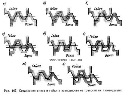
In the same way, you can ensure the screwability of the threads of parts if the angle of the profile of one of them or the position of this profile is incorrect. For example, if the profile angle of the screw is less than expected, which excludes the possibility of the screw being screwed together with the correct nut (Fig. 167, d), then by reducing the average diameter of this screw, these parts can be screwed together (Fig. 167, e). In this case, the contact of the screw thread and the nut occurs only along the upper sections of the side of the screw thread profile and along the lower sections of the nut thread profile.
By reducing the average diameter of a screw with an incorrect profile position (Fig. 167, and) It is also possible to obtain the screwability of a given screw with a nut, however, even in this case, the contact surface of the threads of the screw and the nut may be insufficient for a high-quality threaded connection (Fig. 167, h).
Construction of thread tolerances. Difficulties associated with checking the thread being cut arise mainly when measuring its pitch and profile. Indeed, if all three diameters of external threads can be checked with sufficient accuracy in most cases of practice using micrometers, then to check the pitch and angle of the thread profile accordingly (in terms of accuracy), more complex measuring instruments and even instruments are required. Therefore, when manufacturing threaded parts, tolerances are set only for thread diameters; permissible errors in the pitch and profile are taken into account in the tolerance for the average diameter, because, as shown above, errors in the pitch and profile can always be eliminated by changing the average diameter of one of the threaded parts.
The tolerance on the average diameter is set so that with small errors in the pitch or profile angle, the screw and nut are screwed together without compromising the strength of the threaded connection.
Tolerances on the outer and inner diameters of the screw and nut are assigned such that a gap is obtained between the top of the screw thread profile and the corresponding root of the nut thread.
The numerical values of these tolerances are assumed to be large, exceeding approximately twice the tolerances for the average diameter.
Tolerances of metric and inch threads. For metric threads with large and small pitches for diameters from 1 to 600 mm, according to GOST 9253-59, three accuracy classes are established: first (cl./), second (Cl. 2) and third (cl. 3), and for threads with fine pitches also class 2a (Cl. 2a). These designations were indicated on previously released drawings. In the new GOST 16093-70, accuracy classes are replaced by accuracy grades, which are assigned the designations: h, g, e And d for bolts and N And G for nuts.
For inch and pipe threads, two accuracy classes are established - the second (Cl. 2) and third (Cl. 3).
Tolerances of trapezoidal threads. For trapezoidal threads, three accuracy classes are established, designated: class 1, cl. 2, class 3, cl. ZH.
2.2. Size tolerance. Tolerance field
Size tolerance is the difference between the largest and smallest limit sizes or the algebraic difference between the upper and lower deviations. The tolerance is denoted by IT (International Tolerance) or TD - hole tolerance and Td - shaft tolerance.
The size tolerance is always positive. The size tolerance expresses the spread of actual dimensions ranging from the largest to the smallest limiting dimensions; it physically determines the magnitude of the officially permitted error in the actual size of a part element during its manufacturing process.
The tolerance field is a field limited by upper and lower deviations. The tolerance field is determined by the size of the tolerance and its position relative to the nominal size. With the same tolerance for the same nominal size, there may be different tolerance fields.
For a graphical representation of tolerance fields, allowing you to understand the relationship between nominal and maximum dimensions, maximum deviations and tolerance, the concept of the zero line was introduced.
The zero line is the line corresponding to the nominal size, from which the maximum deviations of dimensions are plotted when graphically depicting tolerance fields. If the zero line is located horizontally, then on a conventional scale, positive deviations are laid upward, and negative deviations are laid down from it. If the zero line is located vertically, then positive deviations are plotted to the right of the zero line.
The tolerance fields of holes and shafts can occupy different locations relative to the zero line, which is necessary to create different fits.
There is a distinction between the beginning and the end of the tolerance field. The beginning of the tolerance field is the boundary that corresponds to the largest volume of the part and makes it possible to distinguish suitable parts from correctable unsuitable parts. The end of the tolerance zone is the boundary that corresponds to the smallest volume of the part and allows us to distinguish suitable parts from irreparable unsuitable ones.
For holes, the beginning of the tolerance field is determined by the line corresponding to the lower deviation, the end of the tolerance field by the line corresponding to the upper deviation. For shafts, the beginning of the tolerance field is determined by the line corresponding to the upper deviation, the end of the tolerance field - by the line corresponding to the lower deviation.
2.3. Formation of tolerance and landing fields
The tolerance field is formed by a combination of one of the main relations with tolerance for one of the qualifications, therefore the symbol of the tolerance field consists of the symbol of the main deviation (letter) and the number of the qualification.
Preferred tolerance fields are provided by cutting tools and calibers according to a normal series of numbers, and recommended ones are provided only by calibers. Additional tolerance fields are fields of limited application and are used when the use of the main tolerance fields does not allow the requirements for the product to be met.
The ESDP provides for all groups of fits: with clearance, interference and transitional. The fits do not have names reflecting structural, technological or operational properties, but are presented only in symbols of the combined tolerance fields of the hole and shaft.
Fittings are typically used in a hole system (preferably) or a shaft system.
All fits in the hole system for the given nominal dimensions of the mates and their qualities are formed by the tolerance fields of the holes with constant basic deviations and no different basic deviations of the shafts.
For fits with a gap in the system, holes are used according to shaft tolerances with main deviations from a to h inclusive.
For transitional fits in the hole system, no shaft tolerances are used with the main deviations k, t, p.
For interference fits in the hole system, shaft start fields with main deviations from p to zc are selected.
For fits in the shaft system for given nominal sizes and mating qualities, tolerance fields with constant main deviations h of the shaft and different main deviations of the holes are used.
For clearance fits in the shaft system, hole tolerance fields with main deviations from A to H inclusive are selected.
For transitional fits in the shaft system, fields up to the openings of the holes with the main deviations Js, K, M, N are used.
For the range from 1 to 500 mm, 69 recommended fits are identified in the hole system, of which 17 are preferred, and in the shaft system there are 59 recommended fits, including 11 preferred.
Chapter 3. Tolerance and landing systems
Taking into account the experience of use and the requirements of national tolerance systems, the ESDP consists of two equal systems of tolerances and fits: the hole system and the shaft system.
The identification of the named systems of tolerances and landings is caused by the difference in the methods of forming landings.
Hole system - a system of tolerances and fits in which the maximum hole dimensions for all fits for a given nominal size dH of mate and quality remain constant, and the required fits are achieved by changing the maximum shaft dimensions.
Shaft system is a system of tolerances and fits in which maximum dimensions shaft for all fits for a given nominal mating size and quality remain constant, and the required fits are achieved by changing the maximum hole dimensions.
The hole system has a wider application compared to the shaft system, which is due to its technical and economic advantages at the design development stage. To process holes of different sizes, it is necessary to have different sets of cutting tools (drills, countersinks, reamers, broaches, etc.), and shafts, regardless of their size, are processed with the same cutter or grinding wheel. Thus, the hole system requires significantly lower production costs both in the process of experimental mating processing and in conditions of mass or large-scale production.
The shaft system is preferable to the hole system, when the shafts do not require additional marking processing, but can be assembled after the so-called blank technological processes.
The shaft system is also used in cases where the hole system does not allow the required connections to be made with given design solutions.
When choosing a landing system, it is necessary to take into account the tolerances for standard parts and components of products: in ball and roller bearings, the fit of the inner ring on the shaft is carried out in the hole system, and the fit of the outer ring in the product body is in the shaft system.
A part whose dimensions do not change for all fits, with unchanged nominal size and quality, is usually called the main part.
In accordance with the pattern of formation of fits, in the hole system the main part is the hole, and in the shaft system the main part is the shaft.
The main shaft is a shaft whose upper deviation is zero.
The main hole is a hole whose lower deviation is zero.
Thus, in the hole system the non-main parts will be shafts, in the shaft system - holes.
The location of the tolerance fields of the main parts must be constant and independent of the location of the tolerance fields of non-main parts. Depending on the location of the tolerance field of the main part relative to the nominal size of the mate, extremely asymmetrical and symmetrical tolerance systems are distinguished.
ESDP is an extremely asymmetrical tolerance system, in which the Tolerance is set “into the body” of the part, i.e. plus - in the direction of increasing the size from the nominal one for the main hole and minus - in the direction of decreasing the size from the nominal one for the main shaft.
Extremely asymmetrical tolerance and fit systems have some economic advantages over symmetrical systems, which is associated with providing the main parts with extreme calibers.
It should also be noted that in some cases non-systemic fits are used, i.e. the hole is made in the shaft system, and the shaft is made in the hole system. In particular, a non-system fit is used for the sides of straight spline joints.
3.1. Layout of tolerance fields for standard interfaces
1 Smooth cylindrical connection
|
Parameter |
Meaning |
|
Td = dmax - dmin = es – ei = |
|
|
TD = Dmax – Dmin = ES - EI = |
|
|
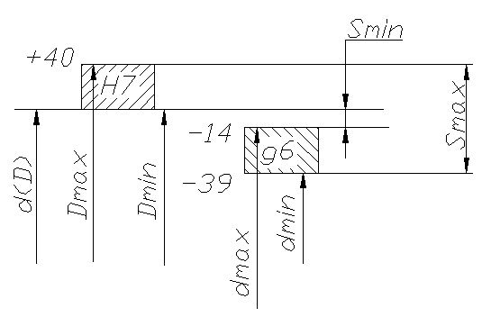
Smax = Dmax - dmin = |
|
|
Smin= Dmin – dmax = |
|
|
Scp = (Smax + Smin) / 2 = |
|
|
TS= Smax – Smin = |
|
|
Nature of pairing |
|
|
Landing system |
Main hole |
|
Parameter |
Meaning |
|
Td = dmax - dmin = es – ei = |
|
|
TD = Dmax – Dmin = ES - EI = |
|
|
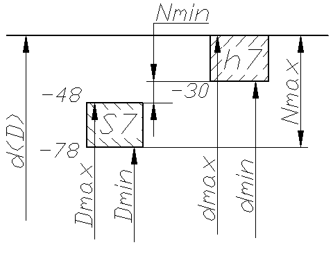
Nmin = dmin - Dmax |
|
|
Nmax = dmax - Dmin |
|
|
Ncp = (Nmax + Nmin) / 2 = |
|
|
TN = Nmax – Nmin = |
|
|
Nature of pairing |
|
|
Landing system |
Main shaft |
|
Parameter |
Meaning |
|
Td = dmax - dmin = es – ei = |
|
|
TD = Dmax – Dmin = ES - EI = |
|
|
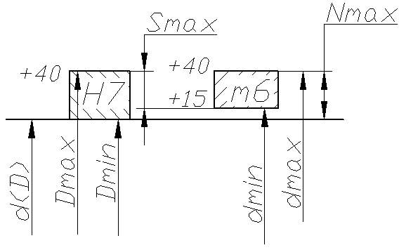
Smax = Dmax - dmin = |
|
|
Nmax = dmax - Dmin = |
|
|
Scp = (Smax + Smin) / 2 = |
|
|
TS = Smax – Smin = |
|
|
Nature of pairing |
Transitional |
|
Landing system |
Main hole |
For a combined fit, we determine the probability of the formation of interference fits and clearance fits. We will perform the calculation in the following sequence.
Let's calculate the standard deviation of the gap (preference), µm
let's define the integration limit
table value of the function Ф(z)= 0.32894
Probability of interference in relative units
P N " = 0.5 + Ф(z) = 0.5 + 0.32894 = 0.82894
Probability of tension in percent
P N = P N " x 100% = 0.82894*100%= 82.894%
Probability of clearance in relative units
P Z "= 1 – P N = 1 - 0.82894 = 0.17106
Probability of gap in percent
P Z = P Z "x 100% = 0.17103*100% = 17.103%

List of used literature
1. Korotkov V.P., Taits B.A. “Fundamentals of metrology and theory of accuracy of measuring devices.” M.: Publishing house of standards, 1978. 351 p.
2. A. I. Yakushev, L. N. Vorontsov, N. M. Fedotov. “Interchangeability, standardization and technical measurements”: – 6th ed., revised. and additional – M.: Mechanical Engineering, 1986. – 352 p., ill.
3. V. V. Boytsova “Fundamentals of standardization in mechanical engineering.” M.: Publishing house of standards. 1983. 263 p.
4. Kozlovsky N.S., Vinogradov A.N. Basics of standardization, tolerances, fits and technical measurements. M., “Mechanical Engineering”, 1979
5. Tolerances and fits. Directory. Ed. V.D. Myagkov. T.1 and 2.L., “Mechanical Engineering”, 1978
The combination of the main deviation and quality forms the tolerance field of the part size . For example:
e8, k6, r6 – shaft tolerance fields (Table 1.2);
D10, M8, R7 – hole tolerance fields (Table 1.3).
Fittings in the drawings are indicated by a fraction: the hole tolerance field is written in the numerator, and the shaft tolerance field is written in the denominator.
The landings are provided in two systems: the main hole landing system and the main shaft landing system.
Main hole landing system or simply hole system - this is a set of fits in which the maximum deviations of the holes are the same (with the same nominal size and quality), and different fits are achieved by changing the maximum deviations of the shafts.
Main hole - this is a hole, which is indicated by the letter H and whose lower deviation is zero (EI = 0). When designating fits in a hole system, the numerator will always contain the main hole “H”, and the denominator will always contain the main shaft deviation intended to form a particular fit.
For example:
– fit a hole in the system with a guaranteed gap;
– fit in the hole system, transitional;
– fit the hole in the system with guaranteed interference.
Main shaft landing system or simply shaft system - this is a set of fits in which the maximum deviations of the shafts are the same (with the same nominal size and the same quality), and different fits are achieved by changing the maximum deviations of the holes.
Main shaft - this is a shaft, which is designated by the letter “ h» and whose upper deviation is zero (es = 0).
When designating fits in a shaft system, the denominator (where the shaft tolerance field is always written) will include the main shaft “ h", and in the numerator is the main deviation of the hole intended to form a particular fit.
For example:
– fit in the shaft system with guaranteed clearance;
– landing in the shaft system, transitional;
– fit in the shaft system with guaranteed interference.
The standard allows any combination of tolerance fields for holes and shafts, for example: ; and etc.
And at the same time, recommended fits have been established for all size ranges, and for sizes 1 – 500 mm the preferred fits have been identified, for example: H7/f7; H7/n6, etc. (see tables 1.2 and 1.3).
Unification of landings makes it possible to ensure uniformity of design requirements for connections and facilitate the work of designers in determining the purpose of landings. By combining various options for the preferred tolerance fields of shafts and holes, you can significantly expand the system’s ability to create various fits without increasing the set of tools, gauges and other technological equipment.
For economic reasons, landings should be prescribed mainly in the hole system and less often in the shaft system. This reduces the range of cutting and measuring tools designed for processing and monitoring holes. Precise holes are machined with expensive cutting tools (countersinks, reamers, broaches). Each of them is used to process only one size with a certain tolerance range. Shafts, regardless of their size, are processed with the same cutter or grinding wheel. In the system, the holes of different maximum sizes are smaller than in the shaft system, and therefore, the range of cutting tools required for processing the holes is smaller.
However, in some cases, for design reasons, it is necessary to use a shaft system, for example, when it is necessary to alternate connections of several holes of the same nominal size, but with different fits on the same shaft, or the socket in the housing for installing the bearing is made according to the shaft system.
In the recommended and preferred fits of precise quality for sizes from 1 to 3150 mm, the hole tolerance is, as a rule, one or two qualities greater than the shaft tolerance, since an accurate hole is technologically more difficult to obtain than an accurate shaft, due to worse heat dissipation conditions, insufficient rigidity, increased wear and difficulty in guiding the cutting tool to process holes.
Tolerances for dimensions up to 500 mm
|
Nominal size, mm |
Quality |
|||||||||||||||
|
Tolerance designation |
||||||||||||||||
|
Tolerance, µm |
||||||||||||||||
|
6 – 10 |
||||||||||||||||
|
10 – 18 |
||||||||||||||||
|
18 – 30 |
||||||||||||||||
|
30 – 50 |
||||||||||||||||
|
50 – 80 |
||||||||||||||||
|
80 – 120 |
||||||||||||||||
The Unified System of Admissions and Landings (USDP) was developed in accordance with a comprehensive program and recommendations of international standards. It extends to mating smooth cylindrical elements and elements limited by parallel planes.
All parts that make up connections, assemblies, assemblies and machines are characterized by geometric dimensions. Dimensions express the numerical value of linear quantities (diameter, length, width, etc.) and are divided into nominal, real and limiting. In mechanical engineering, dimensions are indicated in millimeters. In the connection of elements of two parts, one of them is internal (female), the other is external (male).
In the system of tolerances and fits for smooth joints, every external (male) element is conventionally called shaft and is denoted by lowercase letters of the Latin alphabet, and the internal (encompassing) element is called hole and is indicated by capital letters of the Latin alphabet. Basic terms and definitions are established by GOST 25346-89. Nominal size - size. which serves as the starting point for deviations and relative to which the maximum dimensions are determined. Designated nominal size holes – Dн (D), shaft – dн (d).
Nominal size - is the main size of the part or their connections (the connection involves two parts - a hole and a shaft). It is prescribed based on calculations of parts for strength, wear resistance, rigidity, etc. and based on design, technological and operational considerations. When connected, the two parts have a common nominal size. The values of nominal sizes obtained by calculation should be rounded (as a rule, up).
Actual size – size established by measurement with permissible error. This term was introduced because it is impossible to manufacture a part with absolutely exact required dimensions and measure them without introducing an error. The actual size is indicated for the hole Dд. and for the shaft - dd.
Limit dimensions of the part – two maximum permissible sizes, between which the actual size of a suitable part must be or can be equal to. Size limits, i.e. the range of dispersion of actual sizes is determined by the smallest limiting dimensions (Dmin, dmin) and the largest limiting size (Dmax, dmax) / Comparison of the actual size with the limiting ones makes it possible to judge the suitability of the part.
To simplify the drawings, maximum deviations from the nominal size have been introduced . Maximum size deviation- this is the algebraic difference between the maximum and nominal sizes.
Distinguish between upper and lower limit deviations, using short terms– upper and lower deviation.
Upper deviation (ES – for hole, es – for shaft) - algebraic difference between the largest limit and nominal dimensions: ES = Dmax – Dн, es = dmax – dн
Lower deviation (EI – for the hole, ei – for the shaft) is the algebraic difference between the smallest limit and nominal dimensions:
EI= Dmin – Dн, ei = dmin – dн
Actual deviation called the algebraic difference between the real and nominal sizes. The deviation is positive if the limit or actual size is greater than the nominal size, and negative if the specified dimensions are less than the nominal size.
On mechanical engineering drawings, nominal and maximum linear dimensions and their deviations are indicated in millimeters without specifying a unit, for example 58 +0.013, 42 -0.024, 70±0.2; angular dimensions and their maximum deviations - in degrees, minutes or seconds indicating the unit, for example 0 0 30’40”, 120 o ±20’. A deviation equal to zero is not indicated on the drawings; only one deviation is indicated - positive in place of the upper or negative in place of the lower limit deviation, for example 200 -0.2, 200 +0.2. Maximum deviations in tolerance tables are indicated in micrometers.
The difference between the largest and smallest limit sizes or the absolute value of the algebraic difference between the upper and lower deviations is called the size tolerance. The tolerance is denoted by the letter T, then for the hole - TD, for the shaft - Td: TD=Dmax - Dmin; Td = dmax – dmin.
To simplify, tolerances can be depicted graphically in the form of tolerance fields. In this case, the axis of the product is always positioned according to the diagram. Tolerance field – field limited by upper and lower deviations. Tolerance fields are determined by the tolerance value and its position relative to the nominal size. In a graphical representation, the tolerance field is enclosed between two lines corresponding to the upper and lower deviations relative to the zero line.
Zero line – line corresponding to the nominal size. from which dimensional deviations are plotted when graphically depicting tolerances and fits. If the zero line is located horizontally, then positive deviations are laid up from it, and negative deviations are laid down.
To build tolerance systems, set tolerance unit i (I), which, reflecting the influence of technological, design and metrological factors, expresses the dependence of the tolerance on the nominal size limited by the tolerance, and is a measure of accuracy, as well as the number of tolerance units ( A) , depending on the quality of workmanship (quality) and not depending on the nominal size (19 quality standards are established in the ESDP). Quality– a set of tolerances corresponding to the same degree of accuracy for all nominal sizes. The serial number of quality increases with increasing tolerance: 01; 0; 1; 2….17, quality tolerance is indicated by IT with a serial number, for example IT14.
State standards (GOST 25346-89, GOST 25347-82, GOST 25348-89) replaced the OST system of tolerances and landings, which was in force until January 1980.
Terms are given according to GOST 25346-89"Basic standards of interchangeability. Unified system of tolerances and landings."
Shaft- a term conventionally used to designate the external elements of parts, including non-cylindrical elements;
Hole- a term conventionally used to designate the internal elements of parts, including non-cylindrical elements;
Main shaft- a shaft whose upper deviation is zero;
Main hole- a hole whose lower deviation is zero;
Size- numerical value of a linear quantity (diameter, length, etc.) in selected units of measurement;
Actual size- the size of the element, established by measurement with acceptable accuracy;
Nominal size- the size relative to which deviations are determined;
Deviation- algebraic difference between the size (actual or maximum size) and the corresponding nominal size;
Quality- a set of tolerances considered as corresponding to the same level of accuracy for all nominal sizes;
Landing- the nature of the connection of two parts, determined by the difference in their sizes before assembly.
Gap- this is the difference between the dimensions of the hole and the shaft before assembly, if the hole larger size shaft;
Preload- the difference between the dimensions of the shaft and the hole before assembly, if the size of the shaft is larger than the size of the hole;
Fit tolerance- the sum of the tolerances of the hole and shaft making up the connection;
Tolerance T- the difference between the largest and smallest limit sizes or the algebraic difference between the upper and lower deviations;
IT standard approval- any of the tolerances established by this system of tolerances and landings;
Tolerance field- a field limited by the largest and smallest limit sizes and determined by the tolerance value and its position relative to the nominal size;
Clearance fit- a fit that always creates a gap in the connection, i.e. the smallest limit size of the hole is greater than or equal to the largest limit size of the shaft;
Interference fit- a fit in which interference is always formed in the connection, i.e. the largest maximum hole size is less than or equal to the smallest maximum shaft size;
Transitional fit- a fit in which it is possible to obtain both a gap and an interference fit in the connection, depending on the actual dimensions of the hole and shaft;
Landings in the hole system- fits in which the required clearances and interferences are obtained by combining different tolerance fields of the shafts with the tolerance field of the main hole;
Fittings in the shaft system- fits in which the required clearances and interferences are obtained by combining different tolerance fields of the holes with the tolerance field of the main shaft.
Tolerance fields and corresponding maximum deviations are established by various ranges of nominal sizes:
up to 1 mm- GOST 25347-82;
from 1 to 500 mm- GOST 25347-82;
over 500 to 3150 mm- GOST 25347-82;
over 3150 to 10,000 mm- GOST 25348-82.
GOST 25346-89 establishes 20 qualifications (01, 0, 1, 2, ... 18). Qualities from 01 to 5 are intended primarily for calibers.
The tolerances and maximum deviations established in the standard refer to the dimensions of parts at a temperature of +20 o C.
Installed 27
main shaft deviations and 27
main hole deviations. The main deviation is one of two maximum deviations (upper or lower), which determines the position of the tolerance field relative to the zero line. The main one is the deviation closest to the zero line. The main deviations of holes are indicated in capital letters of the Latin alphabet, shafts - in lowercase letters. Layout diagram of the main deviations indicating the grades in which it is recommended to use them, for sizes up to 500
mm is given below. The shaded area refers to the holes. The diagram is shown in abbreviation.

Landing appointments. Landings are selected depending on the purpose and operating conditions of equipment and mechanisms, their accuracy, and assembly conditions. In this case, it is necessary to take into account the possibility of achieving accuracy using various methods of processing the product. Preferred plantings should be applied first. Plantings are mainly used in hole systems. Shaft system fits are appropriate when using some standard parts (for example, rolling bearings) and in cases where a shaft of constant diameter is used along the entire length to install several parts with different fits on it.
The fit tolerances of the hole and shaft should not differ by more than 1-2 grades. A larger tolerance is usually assigned to the hole. Clearances and interferences should be calculated for most types of connections, especially for interference fits, fluid bearings and other fits. In many cases, landings can be assigned by analogy with previously designed products that are similar in operating conditions.
Examples of the use of fits, relating mainly to the preferred fits in the hole system for sizes 1-500 mm.
Landings with clearance. Hole combination N with shaft h(sliding fits) are used mainly in fixed joints when frequent disassembly is necessary (replaceable parts), if it is necessary to easily move or rotate parts relative to each other when setting or adjusting, to center the fixedly fastened parts.
Landing H7/h6 apply:
For replacement gears in machine tools;
- in connections with short working strokes, for example for spring valve shanks in guide bushings (H7/g6 fit is also applicable);
- for connecting parts that must move easily when tightened;
- for precise direction during reciprocating movements (piston rod in guide bushings of high-pressure pumps);
- for centering housings for rolling bearings in equipment and various machines.
Landing H8/h7 used for centering surfaces with reduced alignment requirements.
Fittings H8/h8, H9/h8, H9/h9 are used for fixedly fixed parts with low requirements for precision of mechanisms, small loads and the need to ensure easy assembly (gears, couplings, pulleys and other parts connected to the shaft with a key; rolling bearing housings , centering of flange connections), as well as in moving joints with slow or rare translational and rotational movements.
Landing H11/h11 used for relatively roughly centered fixed connections (centering flange covers, fixing overhead jigs), for non-critical hinges.
Landing H7/g6 characterized by a minimum guaranteed gap compared to others. Used in moving joints to ensure tightness (for example, a spool in the sleeve of a pneumatic drilling machine), precise direction or for short strokes (valves in a valve box), etc. In particularly precise mechanisms, fits are used H6/g5 and even H5/g4.
Landing Н7/f7 used in plain bearings at moderate and constant speeds and loads, including in gearboxes; centrifugal pumps; for gear wheels rotating freely on shafts, as well as wheels engaged by couplings; for guiding pushers in internal combustion engines. A more accurate landing of this type - H6/f6- used for precision bearings, distributors of hydraulic transmissions of passenger cars.
Landings Н7/е7, Н7/е8, Н8/е8 And Н8/е9 used in bearings at high rotation speeds (in electric motors, in the gear mechanism of an internal combustion engine), with spaced supports or a long mating length, for example, for a gear block in machine tools.
Landings H8/d9, H9/d9 used, for example, for pistons in the cylinders of steam engines and compressors, in the connections of valve boxes with the compressor housing (for their dismantling, a large gap is required due to the formation of soot and significant temperature). More precise fits of this type - H7/d8, H8/d8 - are used for large bearings at high rotation speeds.
Landing H11/d11 used for moving joints operating in conditions of dust and dirt (assemblies of agricultural machines, railway cars), in hinged joints of rods, levers, etc., for centering the covers of steam cylinders with joint sealing with ring gaskets.
Transitional landings. Designed for fixed connections of parts that undergo assembly and disassembly during repairs or due to operating conditions. Mutual immobility of the parts is ensured by keys, pins, pressure screws, etc. Less tight fits are prescribed when there is a need for frequent disassembly of the joint, when inconvenience requires high centering accuracy, and when subject to shock loads and vibrations.
Landing N7/p6(blind type) gives the most durable connections. Application examples:
For gears, couplings, cranks and other parts under heavy loads, shocks or vibrations in connections that are usually disassembled only during major repairs;
- fitting of adjusting rings on the shafts of small and medium-sized electric machines; c) fit of conductor bushings, mounting pins, and pins.
Landing Н7/к6(tension type) on average gives an insignificant gap (1-5 microns) and ensures good centering without requiring significant effort for assembly and disassembly. It is used more often than other transitional fits: for fitting pulleys, gears, couplings, flywheels (with keys), bearing bushings.
Landing H7/js6(tight type) has larger average gaps than the previous one, and is used instead of it if necessary to facilitate assembly.
Pressure landings. The choice of fit is made based on the condition that, with the least interference, the strength of the connection and transmission, loads are ensured, and with the greatest interference, the strength of the parts is ensured.
Landing Н7/р6 used for relatively small loads (for example, fitting an o-ring to the shaft, which fixes the position of the inner bearing ring in crane and traction motors).
Landings H7/g6, H7/s6, H8/s7 used in connections without fasteners under light loads (for example, a bushing in the connecting rod head of a pneumatic engine) and with fasteners under heavy loads (fitting on the key of gears and couplings in rolling mills, oil drilling equipment, etc.).
Landings H7/u7 And Н8/u8 used in connections without fasteners under significant loads, including alternating loads (for example, connecting a pin with an eccentric in the cutting apparatus of agricultural harvesting machines); with fasteners under very heavy loads (fitting large couplings in rolling mill drives), under small loads but short mating lengths (valve seat in the cylinder head of a truck, bushing in the cleaning lever of a combine harvester).
High precision interference fits Н6/р5, Н6/г5, H6/s5 used relatively rarely and in connections that are particularly sensitive to tension fluctuations, for example, fitting a two-stage bushing onto the armature shaft of a traction motor.
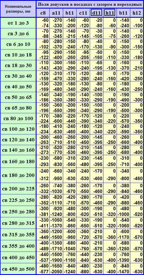
Tolerances of non-matching dimensions. For non-matching dimensions, tolerances are assigned depending on the functional requirements. Tolerance fields are usually located:
- in “plus” for holes (designated by the letter H and the quality number, for example NZ, H9, H14);
- “minus” for shafts (denoted by the letter h and the quality number, for example h3, h9, h14);
- symmetrically relative to the zero line ("plus - minus half the tolerance" is denoted, for example, ±IT3/2, ±IT9/2, ±IT14/2). Symmetrical tolerance fields for holes can be designated by the letters JS (for example, JS3, JS9, JS14), and for shafts - with the letters js (for example, js3, js9, js14).
Tolerances according to 12-18 -th qualities are characterized by non-conjugating or conjugating dimensions of relatively low accuracy. Repeatedly repeated maximum deviations in these qualities are allowed not to be indicated in the dimensions, but to be stipulated by a general entry in the technical requirements.
For sizes from 1 to 500 mm
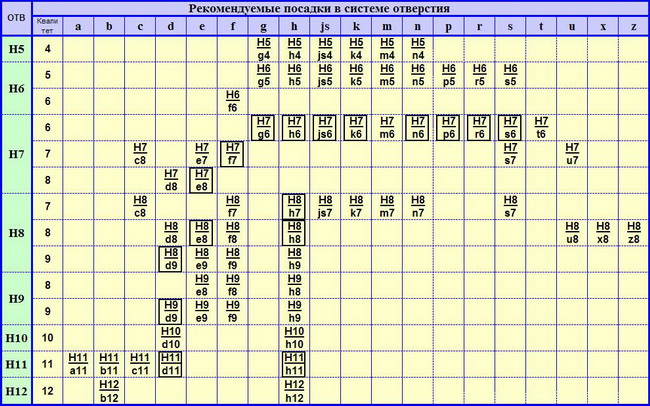
Preferred plantings are placed in a frame.
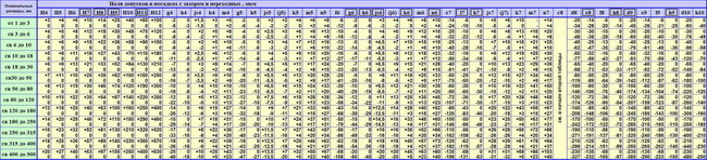
Electronic table of tolerances for holes and shafts indicating the fields according to the old OST system and according to the ESDP.
A complete table of tolerances and fits for smooth joints in hole and shaft systems, indicating tolerance fields according to the old OST system and according to the ESDP:
Related documents:
Angle Tolerance Tables
GOST 25346-89 "Basic norms of interchangeability. Unified system of tolerances and landings. General provisions, series of tolerances and basic deviations"
GOST 8908-81 "Basic standards of interchangeability. Normal angles and angle tolerances"
GOST 24642-81 "Basic standards of interchangeability. Tolerances of shape and location of surfaces. Basic terms and definitions"
GOST 24643-81 "Basic norms of interchangeability. Tolerances of shape and location of surfaces. Numerical values"
GOST 2.308-79 "Unified system of design documentation. Indication on drawings of tolerances of shape and location of surfaces"
GOST 14140-81 "Basic standards of interchangeability. Tolerances for the location of the axes of holes for fasteners"
Dimensional tolerances, fits and fit tolerances.
To begin with, the accuracy of manufacturing a part is characterized by tolerance. And the smaller it is, the more difficult it is to process the part. This is due to increased requirements for the accuracy of the machine, tools, devices, and worker qualifications. It is important to know that an unreasonably larger tolerance reduces the reliability and quality of the product.
The tolerance zone is the field limited by the upper and lower deviations. The tolerance field is determined by the size of the tolerance and its position relative to the nominal size. In a graphical representation, it is concluded between the lines corresponding to the upper and lower deviations of the zero line.
When drawing dimensions with upper and lower deviations on drawings, certain rules must be followed:
Upper or lower deviations equal to zero are not indicated.
The number of characters in the upper and lower deviations is equalized; if necessary, to maintain a single number of characters, zeros are added to the right, for example Æ .
The upper and lower deviations are recorded in two lines, with the upper deviation placed above the lower one; the height of the deviation digits is approximately half that of the nominal size digits;
In the case of a symmetrical location of the tolerance field relative to the zero line, i.e. when the upper deviation is equal in absolute value to the lower deviation, but opposite in sign, their value is indicated after the sign ± in figures equal in height to the figures of the nominal size;
The tolerance field characterizes not only the magnitude of the tolerance, but also its location relative to the nominal size or zero line. It can be located above, below, symmetrically, one-sidedly and asymmetrically relative to the zero line. For clarity, in the drawings of parts above the dimension line after the nominal size, it is customary to indicate the upper and lower deviations in millimeters with their signs, and also for clarity, diagrams of the location of the tolerance field of the shaft or hole relative to the zero line are drawn; in this case, the upper and lower deviations are laid out in micrometers, and not in millimeters.
Fit is the nature of the connection of a part, determined by the size of the resulting gaps or interference. There are three types of plantings:
With a gap
- with interference
- transitional.
Note that the shaft and hole forming the fit have the same nominal size and differ in upper and lower deviations. For this reason, in the drawings above the dimension line, the fit is indicated after the nominal size by a fraction, in the numerators of which the maximum deviations for the hole are written, and in the denominator - similar data for the shaft.
The difference between the dimensions of the shaft and the hole before assembly, if the size of the shaft is larger than the size of the hole, is called interference N. Interference fit – This is a fit that provides interference in the connection, and the hole tolerance is located below the shaft tolerance.
Least Nmin and greatest Nmax interference fits have important meanings for interference fit:
- N min occurs in the connection if in the hole with the largest limit size Dmax the shaft of the smallest maximum size will be pressed d min ;
- N max occurs at the smallest limiting hole size Dmin and the largest maximum shaft size dmax .
The difference between the sizes of the hole and the shaft before assembly, if the size of the hole is larger than the shaft hole, is called gap S. A fit that provides clearance in the connection and the hole tolerance is located above the shaft tolerance is called a clearance fit. It is characterized by the smallest Smin and greatest S max clearances:
- S min occurs at the connection of the hole with the shaft and is formed if in the hole with the smallest limit size Dmin, the shaft with the largest limit size will be installed dmax;
- S max occurs at the largest limiting hole size Dmax and the smallest maximum shaft size d min .
The difference between the largest and smallest clearances or the sum of the tolerances of the hole and shaft making up the joint is called landing clearance.
And a landing in which it is possible to obtain both clearance and interference is called transitional landing. In this case, the tolerance fields of the hole and shaft overlap partially or completely.
Due to the inevitable fluctuation in the dimensions of the shaft and hole from the largest to the smallest values, when assembling parts, fluctuations in clearances and interference occur. The largest and smallest gaps, as well as interference, are calculated using formulas. And the smaller the fluctuation of gaps or interference, the higher the accuracy of fit.
The principle of interchangeability
The design property of a component part of a product that allows it to be used instead of another without additional processing, while maintaining the specified quality of the product it is part of, is called interchangeability. With complete interchangeability, similar parts and products, for example, bolts, studs, can be manufactured and installed in “their places” without additional processing or pre-fitting.
Along with complete interchangeability, it is allowed to assemble products using methods of incomplete and group interchangeability, adjustment and fitting.
Incomplete interchangeability includes the assembly of products based on theoretical and probabilistic calculations.
With group interchangeability, parts manufactured on common machine tools with technologically met tolerances are sorted by size into several size groups; then check the assembly of parts of the same group number.
The regulation method involves the assembly with regulation of the position or dimensions of one or more individual, pre-selected parts of the product, called compensators.
The fitting method is the assembly of products with the fitting of one and the assembled parts. Interchangeability ensures high quality of products and reduces their cost, while contributing to the development of advanced technology and measuring technology. Without interchangeability, modern production is impossible. Interchangeability is based on standardization- finding solutions to recurring problems in the field of science, technology and economics, aimed at achieving the optimal degree of ordering in a certain area. Standardization is aimed at improving the management of the national economy, increasing the technical level and quality of products, etc. The main task of standardization is to create a system of normative and technical documentation that establishes requirements for standardization objects, mandatory for use in certain areas of activity. The most important regulatory and technical document of standardization is a standard developed on the basis of the achievements of domestic and foreign science, technology, and advanced technology and providing solutions that are optimal for the economic and social development of the country.
Tolerances and landings are standardized by state standards included in two systems: ESDP - “Unified System of Tolerances and Landings” and ONV - “Basic Standards of Interchangeability”. ESDP applies to tolerances and fits in the dimensions of smooth elements of parts and to fits formed when connecting these parts. ONV regulates the tolerances and fits of keyed, splined, threaded and conical connections, as well as gears and wheels.
Tolerances and fits are indicated in drawings and sketches technological maps and in other technological documentation. Based on tolerances and fits, technological processes for manufacturing parts and controlling their dimensions, as well as assembling products, are developed.
On the working drawing, the parts are marked with dimensions called nominal, maximum deviations of dimensions and symbols tolerance fields. The nominal hole size is indicated by D, and the nominal shaft size is d. In cases where the shaft and hole form one connection, the nominal size of the connection is taken as the total size of the shaft and hole, designated d(D). The nominal size is selected from a number of normal linear dimensions according to GOST 6636-69. limiting the number of sizes used. For sizes in the range 0.001-0.009 mm installed row: 0.001; 0.002; 0.003;..0.009 mm. There are four main rows of normal sizes (Ra5; Ra10; Ra20; Ra40) and one row of additional sizes. Rows with a larger gradation of sizes are preferable, i.e. row Ra5 will reduce to prefer a row Ra10 etc.
It is almost impossible to process a part exactly to its nominal size due to numerous errors affecting the processing web. The dimensions of the workpiece differ from the specified nominal size. Therefore, they are limited to two marginal sizes, one of which (larger) is called the largest maximum size, and the other (smaller) is called the smallest maximum size. The largest maximum hole size is indicated by Dmax, shaft dmax; correspondingly the smallest maximum hole size Dmin, and shaft d min .
Measuring a hole or shaft with a permissible error determines its actual size. A part is suitable if its actual size is greater than the smallest limit size, but does not exceed the largest limit size.
In the drawings, instead of maximum dimensions, two maximum deviations are indicated next to the nominal size, for example .
Deviation is the algebraic difference between the dimensions and the corresponding nominal size. Thus, the nominal size also serves as the starting point for deviations and determines the position of the zero line.
Real deviation is the algebraic difference between the actual and nominal size.
Maximum deviation- algebraic difference between real and nominal sizes. One of the two maximum deviations is called upper, and the other is called lower.
The upper and lower deviations can be positive, i.e. with a plus sign, negative, i.e. with a minus sign, and equal to zero.
Zero line is a line corresponding to the nominal size, from which dimensional deviations are plotted when graphically depicting tolerances and fits (GOST 25346-82). If the zero line is located horizontally, then a positive deviation is laid up from it, and a negative one is laid down.
ESDP standards apply to smooth mating and non-mating elements of parts with nominal dimensions up to 10,000 mm (Table 1)
Table 1 ESDP standards
Name | ||||||||||||||||||||||||||||||||||||||
ESDP. General position, series of tolerances for main deviations | ||||||||||||||||||||||||||||||||||||||
ESDP. Rows of tolerances, main deviations and tolerance fields for sizes over 3150 mm | ||||||||||||||||||||||||||||||||||||||
ESDP. Tolerance fields for plastic parts | ||||||||||||||||||||||||||||||||||||||
HE IS IN. Maximum dimensional deviations with unspecified tolerances | Classes (levels, degrees) of accuracy in the ESDP are called qualifications, which distinguishes them from accuracy classes in the OST system. Quality(degree of accuracy) - the level of gradation of system tolerance values. Tolerances in each grade increase with increasing nominal dimensions, but they correspond to the same level of accuracy, determined by the grade (its serial number). For a given nominal size, the tolerance for different grades is not the same, since each grade determines the need to use certain methods and means of processing products. The ESDP establishes 19 qualifications, designated by a serial number: 01; 0; 1; 2; 3; 4; 5; 6; 7; 8; 9; 10; eleven; 12; 13; 14; 15; 16 and 17. The highest accuracy corresponds to quality 01, and the lowest - quality 17. The accuracy decreases from quality 01 to quality 17. Quality tolerance is conventionally designated in capital Latin letters IT with the quality number, for example, IT6 - 6th quality tolerance. In what follows, the word tolerance refers to the tolerance of the system. Qualities 01, 0 and 1 are provided for assessing the accuracy of plane-parallel gauge blocks, and qualifications 2, 3 and 4 - for assessing smooth plug gauges and staple gauges. The dimensions of parts of high-precision critical connections, for example, rolling bearings, crankshaft journals, parts connected to rolling bearings of high accuracy classes, spindles of precision and precision metal-cutting machines and others are carried out according to the 5th and 6th qualifications. Qualities 7 and 8 are the most common. They are provided for the dimensions of precise critical connections in instrumentation and mechanical engineering, for example parts of internal combustion engines, automobiles, aircraft, metal-cutting machines, and measuring instruments. The dimensions of parts of diesel locomotives, steam engines, hoisting and transport mechanisms, printing, textile and agricultural machines are mainly carried out according to the 9th qualification. Quality 10 is intended for the dimensions of non-critical connections, for example, for the dimensions of parts of agricultural machines, tractors and wagons. The dimensions of parts forming non-critical connections, in which large gaps and their fluctuations are permissible, for example, the dimensions of covers, flanges, parts obtained by casting or stamping, are assigned according to the 11th and 12th qualifications. Qualities 13-17 are intended for non-critical dimensions of parts that are not included in connections with other parts, i.e. for free sizes, as well as for interoperational dimensions. Tolerances in qualifications 5-17 are determined by the general formula: 1Tq = ai, (1) Where q- number of qualifications; A- dimensionless coefficient established for each quality and not dependent on the nominal size (it is called the “number of tolerance units”); і - tolerance unit (µm) - a multiplier depending on the nominal size; for sizes 1-500 µm
for sizes St. 500 to 10,000 mm
Where D with- geometric mean of boundary values
Where Dmin And Dmax– the smallest and largest limit value of the range of nominal sizes, mm. For a given quality and range of nominal sizes, the tolerance value is constant for shafts and holes (their tolerance fields are the same). Starting from the 5th qualification, the tolerances when moving to an adjacent less accurate qualification increase by 60% (the denominator of the geometric progression is 1.6). After every five qualifications, tolerances increase 10 times. For example, for parts of nominal sizes St. 1 to 3 mm 5th qualification admission IT5 = 4 µm; after five qualifications it increases 10 times, i.e. IT1O =.40 µm etc. Intervals of nominal sizes in the ranges of St. 3 to 180 and St. 500 to 10000 mm in the OST and ESDP systems they are the same. In the OST system up to 3 mm The following size intervals are established: up to 0.01; St. 0.01 to 0.03; St. 0.03 to 0.06; St. 0.06 to 0.1 (exception); from 0.1 to 0.3; St. 0.3 to 0.6; St. 0.6 to 1 (exception) and from 1 to 3 mm. Interval St. 180 to 260 mm divided into two intermediate intervals: St. 180 to 220 and St. 220 to 260 mm. Interval -260 to 360 mm divided into intervals: St. 260 to 310 and St. 310 to 360 mm. Interval St. 360 to 500 mm divided into intervals: St. 360 to 440 and St. 440 to 500 mm. When converting accuracy classes according to OST to qualifications according to ESDP, you need to know the following. Since in the OST system tolerances were calculated using formulas that differed from formulas (2) and (3), there is no exact match of tolerances for accuracy classes and qualifications. Initially, the OST system established accuracy classes: 1; 2; 2a; 3; 3a; 4; 5; 7; 8; and 9. Later, the OST system was supplemented with more accurate classes 10 and 11. In the OST system, the tolerances of shafts of accuracy classes 1, 2 and 2a are set smaller than for holes of the same accuracy classes. This is due to the difficulty of processing holes compared to shafts. The main deviation is one of two deviations (upper or lower) used to determine the position of the tolerance field relative to the zero line. This deviation is the closest deviation from the zero line. For tolerance fields of the shaft (hole) located above the zero line, the main deviation is the lower deviation of the shaft еѕ (for hole EI) with a plus sign, and for tolerance fields located below the zero line, the main deviation is the upper deviation of the shaft еѕ (for hole ES) with a minus sign. The tolerance zone begins from the main deviation boundary. The position of the second boundary of the tolerance field (i.e., the second maximum deviation) is determined as the algebraic sum of the value of the main deviation and the accuracy grade tolerance. There are 28 main deviations for shafts and the same number of main deviations for holes (GOST 25346 - 82). The main deviations are indicated by one or two letters of the Latin alphabet: for the shaft - in lowercase letters from a to zc, and for the hole - in capital letters from A to ZC (Fig. 1, d). The values of the main deviations are given in the tables. The main deviations of the shafts from a to g (the upper deviations е* with a minus sign) and the main deviation of the shaft h (еs equal to zero) are intended to form tolerance fields for the shafts in fits with clearance; from ј (ј *) to n - in transitional fits from р to zс (lower deviations еі with a plus sign) - in interference fits. Similarly, the main deviations of the holes from A to G (lower deviations EI with a plus sign) and the main deviation of the hole H (for it EI = 0) are intended to form tolerance fields for holes in clearance fits; from Ј (Ј *) to N - in transitional fits and from P to ZС (upper deviations ES with a minus sign) - in interference fits. The letters ј * and Ј * indicate the symmetrical location of the tolerance relative to the zero line. In this case, the numerical values of the upper еѕ (ЭЅ) and lower еі(ЭІ) deviation of the shaft (hole) are numerically equal, but opposite in sign (the upper deviation has a “plus” sign, and the lower one has a “minus” sign). The main deviations of the shaft and holes, indicated by the letter of the same name (for a given size range), are equal in magnitude, but opposite in sign; they increase with increasing value of the size interval. By combining the tolerance fields of shafts and holes, a large number of fits can be obtained. A distinction is made between fits in the hole system and in the shaft system. Fitments in a hole system are fits in which various gaps and interferences are obtained by connecting shafts of different sizes to one main hole (Fig. 1, a), the tolerance field of which (for a given quality and size range) is constant for the entire set of fits. The tolerance field of the main hole is located invariably relative to the zero line so that its lower deviation EI = 0 (it is the main deviation H), and the upper deviation ES with a + “plus” sign is numerically equal to the tolerance of the main hole. The tolerance fields of the shafts in clearance fits are located below the zero line (under the tolerance field of the main hole), and in interference fits - above the tolerance field of the main hole (Fig. 1, b). In transitional fits, the tolerance fields of the shafts partially or completely overlap the tolerance field of the main hole. Fitments in a shaft system are fits in which various gaps and interferences are obtained by connecting holes of different sizes to one main shaft, the tolerance range of which (for a given quality and size range) is constant for the entire set of fits. The tolerance field of the main shaft is located invariably relative to the zero line so that its upper deviation еѕ = 0, and the lower deviation еі with a “minus” sign is numerically equal to the tolerance of the main shaft. The tolerance fields of holes in clearance fits are located above the tolerance field of the main shaft, and in interference fits - below the tolerance field of the main shaft. The hole system is characterized by a simpler technology for manufacturing products compared to the shaft system, and therefore it has received preferential use. The shaft system connects rolling bearings to the holes of the bushings or product bodies, as well as the piston pin to the piston and connecting rod, etc. In some cases, to obtain connections with very large gaps, they use combined plantings- fits formed by the tolerance fields of holes from the shaft system and the tolerance fields of shafts from the hole system. For nominal sizes less than 1 and St. 3150 mm, as well as for grades 9-12 with nominal sizes of 1-3150 mm, fits are formed by a combination of tolerance fields for holes and shafts of the same accuracy grade, for example, H6/p6; H7/e7; E8/h8; Н9/е9 and В11/h1. In the 6th and 7th grades with nominal sizes of 1-3150 mm, for technological reasons, it is recommended to select the hole tolerance field one grade coarser than the shaft tolerance field, for example, H7/k6; E8/h7. In addition to the landings indicated in the tables, in technically justified cases, other landings formed from the ESDP tolerance fields are allowed for use. The fit must be related to the hole system or shaft system, and if the tolerances of the hole and shaft are unequal, the hole must have a larger tolerance. The tolerances of the hole and shaft can differ by no more than two grades. The selection and assignment of tolerances and fits is carried out on the basis of calculations of the required clearances or interferences, taking into account the operating experience of such connections. Some examples of the use of preferred ESDP landings for nominal sizes of 1-500 mm are given below (the corresponding names of fits in the OST system are given in parentheses), and the layout of the tolerance fields of shafts and holes of these fits is shown in Fig. 2. The fits H7/h6 and H8/h7 are formed by the tolerance fields of the main shaft and the main hole. The smallest gap is zero, and the largest is the sum of the shaft and hole tolerances. These landings correspond sliding landings OST systems, they are used primarily for fixed connections, often subject to disassembly and adjustment and allowing rotation or longitudinal movement of one part relative to another (for installing replaceable gears in machines and mechanisms, replaceable guide bushings, milling cutters on mandrels, centering housings for rolling bearings, spindle in the drilling machine body). The H8/h8 fit is used when installing parts on shafts that transmit torques through pins and keys, for fixed axles and pins in supports, for connecting parts that must move easily during adjustment and adjustment, followed by tightening in the working position. Fit H11/h11 is low precision and is intended for relatively roughly centered fixed connections (for centering flanges of covers and valve bodies, for connections whose parts are subject to welding; for gland covers in housings, for connections of spacer bushings, etc.). In fixed joints, these fits are used for non-critical hinges and rollers. The H7/g6 (movement) fit is used in precision moving joints, in which it is necessary to ensure tightness when moving one part into another, as well as smooth and accurate movements; for sliding bearings of particularly precise mechanisms under low loads and operating at a constant temperature; for example, spindles of precision machines, mechanisms and dividing heads in their guides, replaceable bushings in jigs, movable gears on gearbox shafts, plunger and hydraulic pairs. Landings H7/f7 and F8/h6 (running) are intended for shaft supports rotating at a moderate angular velocity (frequency up to 150 rad/s) under constant load in magnitude and direction; for supports with translational movement of one part relative to another; for fixed connections with low accuracy of centering of parts, allowing for their easy assembly and disassembly (piston in a hydraulic cylinder; gears and couplings moved on shafts; plain bearings of light and medium-sized machines, gearboxes, pumps, etc.) Landings H7/e8, H8/e8 and E9/h8 are characterized by large gaps, therefore they ensure free rotation under significant loads and angular velocities (over 150 rad/s). They are used when the shaft supports are spaced apart and the length of the supports is increased, for example, for sleeve bearings of turbogenerator shafts and electric machines. Fittings H11/d11 are intended for low-precision movable connections and for stationary, roughly centered connections operating under loaded and sprayed conditions. Plantings H7/p6 and P7/h6 are characterized by minimal guaranteed interference. They are intended for fixed connections transmitting relatively small axial gains or small torques, for mating shafts with thin-walled tubes that do not allow large deformations, for connecting parts made of non-ferrous metals and light alloys, for centering heavily loaded shafts with bushings with additional fastening of the parts being connected. Fittings H7/s6 H7/r6 (press fits) for fixed joints carrying medium loads without additional fastening of the parts being connected. The N7/nb and N7/h6 landings (corresponding to a blind fit) provide only interference in the connections (the probability of getting gaps is extremely low). These fits are used when centering parts in fixed joints that absorb vibrations and shocks. Reliable interference fit is guaranteed by additional fastening of parts using screws, pins, etc. The connection is rarely disassembled (during major repairs). For example, gears and couplings on shafts, bronze rims of worm wheels, conductor bushings in machine tools, piston pins in engine piston bosses, a fan hub on a shaft. Landings H7/k6 and K7/h6 (stressed) provide an average gap close to zero. The probability of getting gaps and interference in the connection is approximately the same. Due to errors in the shape of the surfaces being connected, especially with a connection length exceeding three diameters, gaps are not felt. Therefore, these fits are used for precise centering of connected parts, for example, stationary gears on the shafts of metal-cutting machines, bushings in the connecting rod head of a tractor engine; pulleys, flywheels and levers on shafts; removable couplings on shafts. Fittings H7/ј * 6 and Јѕ7/hb (tight) provide only gaps in the joints (the likelihood of interference is low). However, due to the influence of errors in the shape and location of surfaces, when assembling the joint, it is necessary to apply force using a wooden hammer. The fit is prescribed for easily disassembled, fixed, centering connections (handwheels on shafts, bearing cups in housings). Parts are manufactured according to drawings, on the dimension lines of which, after the nominal dimensions, size tolerances are indicated in the form of upper and lower maximum deviations or symbols of tolerance fields. GOST 25346-82 provides three options for setting the size tolerance: or Æ 40H7/e8) or to the line Æ 40N7-e8.In the latter case, the designations relating to the hole are placed first, and after the dash - to the shaft. The third option is used when assigning standard maximum deviations for sizes that are not included in the series of nominal linear dimensions [for example, 41.5N8( +0.039 )]; when assigning maximum deviations not provided for by GOST 25347-82 and GOST 25348-82 [for example, 50x10 ()]. Plastic parts are widely used in mechanical engineering and instrument making. Gears, pulleys, flywheels, bearing shells and bushings, covers, tanks, parts of measuring instruments, electrical insulating parts, etc. are made from plastics. However, the specificity of plastics as structural materials required the development of a system of tolerances and fits for parts made from these materials. The dimensions of plastic parts change significantly under the influence of temperature and humidity. Therefore, the tolerances and maximum deviations of plastic parts established by GOST 25349-82 apply to parts whose dimensions are determined at a temperature of 20 ° C and a relative air humidity of 65%. After manufacturing, a plastic part must be kept for 6-12 hours before dimensional control begins. Tolerance fields for plastic parts are given in the tables; they are a restrictive selection from the totality of tolerance fields in accordance with GOST 25347-82 and, in addition, include tolerance fields provided for by GOST 25349-82. Numerical values of maximum deviations corresponding to tolerance fields not provided for by GOST 25347-82. It is recommended to designate fits in connections between plastic parts and plastic or metal parts according to the tables. The shape of parts, such as shafts and bushing holes, is characterized by various surfaces, divided into nominal and real. Nominal surface- an ideal surface, the nominal shape of which is specified by a drawing or other technical documentation. Table 2 Standards for tolerances of shape and location of surfaces
The actual surfaces of the part are obtained after manufacturing. The real surface differs from the nominal one by the deviation D of the surface shape. Deviation of surface shape D is called the deviation of the shape of the real surface from the shape of the nominal surface. Along with the normalization of deviations in the shape of surfaces, the normalization of the surface profile is provided. Surface profile- the line of intersection of a surface with a plane or a given surface. A distinction is made between nominal and real surface profiles. Nominal profile- profile of the nominal surface, and real profile- real surface. Deviation D of the profile is the deviation of the real profile from the nominal one. Deviations of the surface shape are measured from the adjacent surface, which has the shape of a nominal surface, is in contact with the real surface and is located outside the part so that the deviation from it of the most distant point of the real surface within the normalized area has a minimum value. The deviation of the surface profile is assessed in the same way. Surface roughness is not taken into account when determining shape deviations. Each of the sizes forming a dimensional chain is called a link. The links of the dimensional chain can be any linear or angular parameters: diametrical dimensions, distances between surfaces or axes, gaps, tensions, overlaps, backlashes, deviations in the shape and location of surfaces (axes), etc. Any dimensional chain has one initial (closing) and two or more constituent links. The initial link is the link to which the basic requirement of accuracy is imposed, which determines the quality of the product in accordance with the technical specifications. In the process of processing or assembling a product, the original link is usually obtained last, completing the dimensional chain. In this case, such a link is called a closing link. Thus, the closing link is not directly executed, but is the result of the execution (manufacturing) of all other links in the chain. All other links are called components; changing them also changes the closing link. The constituent links of the dimensional chain are divided into two groups. The first group includes links, with an increase in which (assuming other constants) the closing link increases. Such links are called increasing links. The second group includes links, with an increase in which the closing link decreases. Such links are called reducing links.
Calculation of dimensional chains is a necessary stage in the design, production and operation of a wide class of products. Using the theory of dimensional chains, the following design, technological and metrological problems can be solved:
Dimensional chains are used to solve direct and inverse problems that differ in the sequence of calculations. Direct task. Based on the given nominal value and tolerance (deviations) of the initial link, determine the nominal dimensions, tolerances and maximum deviations of all component links of the dimensional chain. Inverse problem. Based on the established nominal dimensions, tolerances and maximum deviations of the component links, determine the nominal size, tolerance and maximum deviations of the closing link. This task relates to the verification calculation of the dimensional chain. By solving the inverse problem, the correctness of the solution to the direct problem is verified. The following methods exist to achieve the specified accuracy of the source link:
Calculations of dimensional chains can be made:
The classification of the methods used to achieve the specified accuracy of the initial link is given in the table. When choosing a method for achieving a given accuracy, it is necessary to take into account the functional purpose of the product, its design and technological features, the cost of manufacturing and assembly, operational requirements, type of production, its organization and other requirements. The specified accuracy must be achieved with the lowest technological and operating costs. All other things being equal, it is recommended to choose, first of all, such methods of achieving a given accuracy in which the assembly is carried out without selection, adjustment and adjustment and the assembled products meet all the requirements of interchangeability, i.e. use the method of complete interchangeability or the probabilistic method (see Table 5.). Table.5 Classification of methods for achieving the specified accuracy of the initial link (according to GOST 16319-80)
3.1. Maximum dimensional deviations should be indicated immediately after the nominal dimensions. Maximum deviations of linear and angular dimensions of relatively low accuracy may not be indicated directly after the nominal dimensions, but may be specified by a general entry in the technical requirements of the drawing, provided that this entry unambiguously defines the values and signs of the maximum deviations. A general record of maximum deviations of dimensions with unspecified tolerances must contain symbols of maximum deviations of linear dimensions in accordance with GOST 25346 (for deviations by qualifications) or in accordance with GOST 25670 (for deviations by accuracy classes). Symmetrical maximum deviations assigned according to qualifications should be designated ± indicating the qualification number. Designations of one-sided maximum deviations by qualifications. assigned only for round holes and shafts (option 4 according to GOST 25670-82) are supplemented with a diameter sign (Æ). Examples of general records corresponding to options in accordance with GOST 25670 for grade 14 and (or) accuracy class “medium” are given in table. 3: Table 3
|
- Drying organic liquids Wine spirit and its relatives
- Laboratory work: Production of methane and experiments with it Calcium carbide was used to dehydrate ethanol
- Model of error in the form of a random elementary function Mathematical model of measurement results of measurement error
- Questions for subject and object Basic geometric shapes