
What is the maximum size deviation?
Chapter IX. Tolerances and fits, surface roughness
§ 33. Tolerances and landings. Basic concepts and terms
The dimensions indicated by the designer in the drawing cannot be made absolutely accurately. The dimensions of the obtained parts have some error, i.e. some discrepancy with the dimensions indicated in the drawing. The magnitude of the error depends on the accuracy of the machine on which the part was processed; on the accuracy and amount of wear of tools and devices; from the deformation of the part during processing and the properties of its material; on the accuracy of the measuring instrument and a number of other factors. At the same time, for each size certain deviations from the specified value can be allowed without compromising the quality of the product and the interchangeability of its parts and taking into account that the assembled product provides the necessary mating of the connected parts. Therefore, the designer must indicate on the drawing the values of permissible errors that ensure the interchangeability of the component parts of the product and its reliable operation.
Furniture products consist of elements that, during operation, undergo relative movement or are at relative rest. Two elements that are movably or immovably connected to each other are called mating. The surfaces and dimensions along which two parts are connected are called mating surfaces, or mating dimensions, respectively. When connecting mating surfaces, a distinction is made between male and female surfaces and, accordingly, male and female dimensions. For cylindrical joints, the female surface is called the “hole” and the male surface is called the “shaft”. The names "hole" and "shaft" are loosely applied to all male and female surfaces, such as lug and tenon.
The nominal size of a part, assembly or product is the main size that is calculated during design and indicated on the drawing.
Actual size determined by measurement with appropriate measuring instruments received after processing the part.
Limit These are the sizes between which the actual size can fluctuate. The largest limit size is the sum of the nominal size and the upper limit deviation, and the smallest limit size is the sum of the nominal size and the lower limit deviation.
Upper maximum deviation is called the difference between the largest limit and nominal sizes. The lower limit deviation is the difference between the smallest limit and nominal sizes.
Admission is the difference between the largest and smallest maximum dimensions. Tolerance is always positive; this value determines the degree of accuracy of processing parts. Thus, when manufacturing a tenon with a thickness of 10 mm with deviations within +0.35 and +0.10, the size of 10 mm is nominal, a deviation of +0.35 mm is the upper limit deviation, +0.10 mm is the lower limit deviation. The largest limiting tenon size will be 10+0.35=10.35 mm, and the smallest will be 1:0+0.10=10.10 mm. The size tolerance is: 10.35-10.10=0.25 mm. The width of the lugs for this stud will be 10 mm with deviations ranging from 0 to +0.25 mm. The size of 10 mm is also the nominal size of the eye, deviation 0 is the lower limit deviation, +0.25 is the upper limit deviation. The smallest limit size of the eye will be 10+0=10.0 mm, and the largest 10+0.25=10.25 mm. The size tolerance is 10.25-10.0=0.25 mm. The distance between the largest and smallest limit sizes is called the tolerance zone. A graphical interpretation of the tolerance is shown in Fig. 123.

Gap is called the positive difference between the dimensions of the hole and the shaft. For example, thanks to the gap, a table drawer moves freely in its nest. The largest gap is the difference between the largest maximum hole size and the smallest maximum shaft size. The smallest clearance is the difference between the smallest maximum hole size and the largest maximum shaft size.
By interference is the negative difference between the dimensions of the hole and the dimensions of the shaft, which creates a fixed connection after their assembly. The maximum interference is the difference between the smallest maximum dimensions of the hole and the largest maximum dimensions of the shaft. The smallest interference is the difference between the largest maximum hole dimensions and the smallest shaft dimensions.
Free are called incompatible dimensions. Free dimensions also include those dimensions that, after assembling the parts, will undergo changes as a result of subsequent processing of the parts.
Landing called the nature of the interfaces that determine the density or mutual mobility of two or more interconnected parts.
In furniture production, all plantings established by regulatory materials are carried out using the hole system. This system is characterized by the fact that the tolerance field of the hole is directed towards the increase (into the body), and the tolerance field of the shaft is a variable value and depends on the selected fits. The hole size in this case is called the main size, and the shaft size is called the connecting size.
When designing furniture, it is very important to correctly assign maximum dimensional deviations and determine the nature of the fit of mating surfaces. When assigning maximum deviations in the sizes of interchangeable elements, the designer must comply with the following two rules:
1) the drawing must indicate the largest permissible maximum dimensional deviations;
2) requirements for the accuracy of products should not exceed the technical capabilities of production.
Compliance with the first rule is dictated by economic considerations. The designer must strive to ensure that the precision he sets for manufacturing parts does not exceed the accuracy achievable under normal operating conditions, serviceable equipment and standard tool quality.
Compliance with the second rule is dictated by the technical capabilities of production. Sometimes increased requirements for the accuracy of manufacturing parts are due to the fact that the designer has not carefully studied the production conditions. In such cases, often with a more thorough analysis of the design, it is possible to expand the previously recommended maximum deviations without compromising the quality of the manufactured parts. If the conditions of interchangeability require the production of parts with increased precision for a given production, then they resort to joint processing of mating parts or to manual fitting.
The designer assigns maximum deviations in accordance with existing standards, recommendations, or determines them by calculation. The calculated error values must be consistent with the tolerances established during the design of the part. In this case, the following conditions must always be observed:
Δ to ≥ Δ calc,
where Δ k is the tolerance assigned by the designer;
Δ calculated - the value of the dispersion field of dimensional errors, characterizing the distance between the largest and smallest limiting dimensions obtained by calculation.
Chapter 1. Hole system and shaft system. Peculiarities,
differences, advantages…………………………………………………………….3
1.1.The concepts of “shaft” and “hole”………………………………………………………………...3
1.2. Calculation of fit parameters and calibers for mating in
hole and shaft systems…………………………………………………………….6
Chapter 2. Tolerances and fits of keyed connections………………………...10
2.1. Thread tolerances………………………………………………………………………………15
2.2. Size tolerance. Tolerance field…………………………………………..18
2.3. Formation of fields of tolerances and landings……………………………..19
Chapter 3. Tolerance and landing systems………………………………………………………..21
3.1. Layout of tolerance fields for standard interfaces……….23
List of used literature……………………………………………………..30
Chapter 1. Hole system and shaft system. Features, differences, advantages
1.1.The concepts of “shaft” and “hole”
Structurally, any part consists of elements (surfaces) of various geometric shapes, some of which interact (form fits and mates) with the surfaces of other parts, and the rest of the elements are free (non-mating). In the terminology of tolerances and fits, the dimensions of all elements of parts, regardless of their shape, are conventionally divided into three groups: shaft dimensions, hole dimensions, and dimensions not related to shafts and holes.
Shaft is a term conventionally used to designate the external (male) elements of parts, including non-cylindrical elements, and, accordingly, mating dimensions.
Hole is a term conventionally used to designate internal (enclosing) elements of parts, including non-cylindrical elements, and, accordingly, mating dimensions.
For mating elements of parts, based on the analysis of working and assembly drawings, and, if necessary, product samples, the female and male surfaces of the mating parts and, thus, the membership of the mating surfaces in the “shaft” and “hole” groups are established.
For non-mating elements of parts, the establishment of a shaft or a hole is carried out using the technological principle that if, when processing from the base surface, the size of the element increases, then this is a hole, and if the size of the element decreases, then this is a shaft.
The composition of the group of dimensions and elements of parts that do not relate to either shafts or holes is relatively small (for example, chamfers, rounding radii, fillets, protrusions, depressions, distances between axes (etc.).
During assembly, the parts to be connected come into contact with each other by separate surfaces, which are called mating surfaces. The dimensions of these surfaces are called mating dimensions (for example, the diameter of the bushing hole and the diameter of the shaft on which the bushing is seated). A distinction is made between female and male surfaces and, respectively, male and female dimensions. The enclosing surface is usually called the hole, and the male surface is called the shaft.
The interface has one nominal size for the hole and shaft, and the maximum sizes are usually different.
If the actual (measured) dimensions of the manufactured product do not go beyond the largest and smallest maximum dimensions, then the product meets the requirements of the drawing and is made correctly.
The designs of technical devices and other products require different contacts of mating parts. Some parts must be movable relative to others, while others must form fixed connections.
The nature of the connection of parts, determined by the difference between the diameters of the hole and the shaft, creating greater or less freedom of their relative movement or the degree of resistance to mutual displacement, is called fit.
There are three groups of landings: movable (with a gap), fixed (with interference) and transitional (a gap or interference is possible).
The gap is formed as a result of the positive difference between the dimensions of the hole diameter and the shaft. If this difference is negative, then the fit will be an interference fit.
There are the largest and smallest gaps and interferences. The largest clearance is the positive difference between the largest limiting hole size and the smallest limiting shaft size
The smallest gap is the positive difference between the smallest limiting hole size and the largest limiting shaft size.
The greatest interference is the positive difference between the largest maximum shaft size and the smallest maximum hole size.
The minimum interference is the positive difference between the smallest maximum shaft size and the largest maximum hole size.
The combination of two tolerance fields (hole and shaft) determines the nature of the fit, i.e. the presence of a gap or interference in it.
The system of tolerances and fits establishes that in each mate one of the parts (the main one) has any deviation equal to zero. Depending on which of the mating parts is accepted as the main one, a distinction is made between fits in the hole system and fits in the shaft system.
Fittings in a hole system are fittings in which various clearances and tensions are obtained by connecting different shafts to the main hole.
Fittings in a shaft system are landings in which various clearances and interferences are obtained by connecting various holes to the main shaft.
The use of a hole system is preferable. The shaft system should be used where design or economic considerations justify it (for example, installing multiple bushings, flywheels or wheels with different fits on a single smooth shaft).
1.2. Calculation of fit parameters and gauges for mating in hole and shaft systems
1. Deviations of the hole and shaft according to GOST 25347-82:
ES = +25 µm, es = -80 µm
EI = 0; ei = -119 µm
Fig.1. Layout of landing tolerance fields
2. Limit dimensions:
3. Hole and shaft tolerances:
4. Clearances:
5. Average clearance:
6. Clearance tolerance (fit)
7. Designation of maximum dimensional deviations on design drawings:
A) symbol tolerance fields

b) numerical values of maximum deviations:
c) symbol of tolerance fields and numerical values of maximum deviations:
8. Designation of dimensions on working drawings:

9. Calculation of gauges for checking holes and shafts.
Tolerances and deviations of calibers according to GOST 24853-81:
a) for plug gauges
Z = 3.5 µm, Y = 3 µm, H = 4 µm;
b) for clamp gauges
Z 1 = 6 µm, Y 1 = 5 µm, H 1 = 7 µm;

Rice. 2 Layout of caliber tolerance fields
Bore testing gauges
Plug PR
Executive plug size PR:
Average wear  µm;
µm;
Workers can wear the plug up to the following size:
Wear of the plug by the shop inspector is permissible up to the following size:
Cork NOT
Executive plug size NOT:
Shaft test gauges
Executive size of bracket PR:
Average wear  µm;
µm;
Wear of the bracket by workers is permissible up to the following size:
Wear of the bracket by the shop inspector is permissible up to the following size:
Executive staple size NOT
Dimensions on drawings
Introduction
In conditions of mass production, it is important to ensure interchangeability identical parts. Interchangeability allows you to replace a part that breaks during operation of the mechanism with a spare one. The new part must exactly match the size and shape of the one being replaced.
The main condition for interchangeability is the manufacture of parts with a certain accuracy. The accuracy of manufacturing a part should be indicated on the drawings by the permissible maximum deviations.
The surfaces along which parts are connected are called mating . In the connection of two parts that fit into one another, a distinction is made between the female surface and the male surface. The most common connections in mechanical engineering are connections with cylindrical and flat parallel surfaces. In a cylindrical connection, the surface of the hole covers the surface of the shaft (Fig. 1, a). The covering surface is usually called hole , covering – shaft . These same terms hole And shaft conditionally used to designate any other non-cylindrical male and female surfaces (Fig. 1, b).
Rice. 1. Explanation of terms hole And shaft
Landing
Any operation of assembling parts involves the need to connect or, as they say, plant one detail to another. Hence the expression adopted in technology landing to indicate the nature of the connection of parts.
Under the term landing understand the degree of mobility of the assembled parts relative to each other.
There are three groups of landings: with clearance, with interference and transitional.
Landings with clearance
Gap the difference between the sizes of the hole D and the shaft d is called if the size of the hole is larger than the size of the shaft (Fig. 2, a). The gap ensures free movement (rotation) of the shaft in the hole. Therefore, landings with a gap are called movable landings. The larger the gap, the greater the freedom of movement. However, in reality, when designing machines with movable landings, a gap is chosen that will minimize the coefficient of friction between the shaft and the hole.
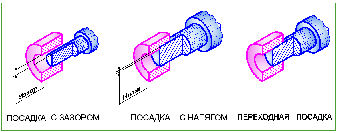
Rice. 2. Landings
Preference fits
For these fits, the hole diameter D is less than the shaft diameter d (Fig. 2, b). In reality, this connection can be made under pressure, when the female part (hole) is heated and (or) the male part (shaft) is cooled.
Preference landings are called fixed landings , since mutual movement of the connected parts is excluded.
Transitional landings
These fits are called transitional because before assembling the shaft and hole it is impossible to say what will happen in the connection - a gap or an interference fit. This means that in transitional fits the hole diameter D can be smaller, larger or equal to the shaft diameter d (Fig. 2, c).
Size tolerance. Tolerance field. Quality of accuracy Basic concepts
Dimensions on part drawings quantify the size of the geometric shapes of a part. Dimensions are divided into nominal, actual and limiting (Fig. 3).
Nominal size - this is the main calculated size of the part, taking into account its purpose and the required accuracy.
Nominal connection size – this is the common (same) size for the hole and shaft that make up the connection. The nominal dimensions of parts and connections are not chosen arbitrarily, but according to GOST 6636-69 “Normal linear dimensions”. In real production when making parts nominal dimensions cannot be maintained and therefore the concept of actual dimensions was introduced.
Actual size – this is the size obtained during the manufacture of the part. It always differs from the nominal value up or down. The permissible limits of these deviations are established by means of maximum dimensions.
Limit dimensions name two boundary values between which the actual size must lie. The larger of these values is called largest size limit, less – smallest size limit. In everyday practice, on drawings of parts, it is customary to indicate maximum dimensions by means of deviations from the nominal.
Maximum deviation is the algebraic difference between the maximum and nominal sizes. There are upper and lower deviations. Upper deviation is the algebraic difference between the largest limit size and the nominal size. Lower deviation is the algebraic difference between the smallest limit size and the nominal size.
The nominal size serves as the starting point for deviations. Deviations can be positive, negative or equal to zero. In tables of standards, deviations are indicated in micrometers (µm). In drawings, deviations are usually indicated in millimeters (mm).
Actual deviation is the algebraic difference between the real and nominal sizes. The part is considered acceptable if the actual deviation of the size being checked is between the upper and lower deviations.
Size tolerance is the difference between the largest and smallest limit sizes or the absolute value of the algebraic difference between the upper and lower deviations.
Under quality understand a set of tolerances that vary depending on the nominal size. 19 qualifications have been established, corresponding to different levels of precision in manufacturing a part. For each qualification, a series of tolerance fields have been constructed
Tolerance field – this is a field limited by upper and lower deviations. All tolerance fields for holes and shafts are indicated by letters of the Latin alphabet: for holes - in capital letters (H, K, F, G, etc.); for shafts - lowercase (h, k, f, g, etc.).
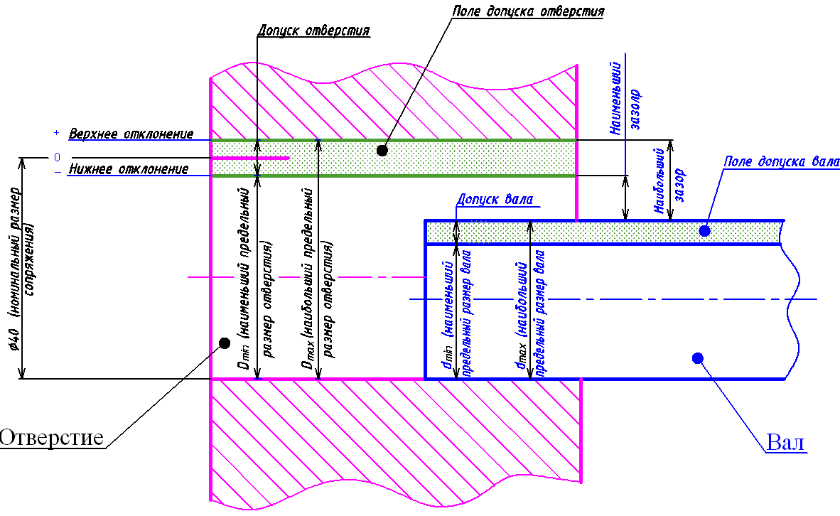
Rice. 3. Explanations of terms
- What documents should an individual entrepreneur have?
- Accounting for individual entrepreneurs - rules and features of independent reporting under different tax regimes Primary documentation for individual entrepreneurs
- Accounting for individual entrepreneurs: features of accounting in individual entrepreneurs?
- How to privatize an apartment, everything about privatization List of documents for privatization of an apartment