
What is the nominal size of the part. Great encyclopedia of oil and gas
Page 1
Actual dimensions differ from nominal ones due to the impossibility of achieving absolute accuracy in the manufacture of parts. Thus, if the nominal diameter of the shaft is 80 mm, and the largest permissible deviation (tolerance) is minus 0 06 mm, then the actual dimensions of the shaft diameters can have any values from 80 to 79 94 mm.
Actual dimensions are determined by direct measurement of the structure.
| Tolerances, clearances and interference. |
The actual size is obtained by measuring the product.
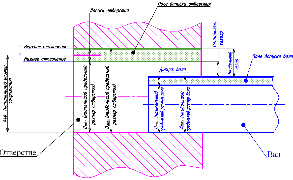
The actual size is the size determined by measurement with a given degree of error. Limit sizes are two parallel size values between which the actual size must lie. The larger of them is called the largest limit size, the smaller one is called the smallest limit size. The difference between the size and its nominal value is called the size deviation - positive if the size is larger than the nominal, and negative if it is smaller than the nominal. The difference between the largest limit size and the nominal size is called the upper limit deviation, and the difference between the smallest limit size and the nominal size is called the lower limit deviation. The maximum deviation is considered positive if the maximum size is larger than the nominal size; negative if the limit size is less than the nominal size; equal to zero if these sizes are the same.
The actual size is between two maximum dimensions. The difference between the largest and smallest limit sizes is called size tolerance. The shaded strip with height BC, equal to the size tolerance, is called the size tolerance field. The upper deviation is the difference between the largest and nominal sizes. The lower deviation is the difference between the smallest and nominal sizes. Actual deviation is called the difference between the actual and nominal sizes. The drawings usually indicate nominal size, upper and lower deviations.
| Tolerances and landings. |
Actual size is the actual size of the part obtained by measurement after processing. The measurement accuracy must correspond to the accuracy class.
Actual size is the size of the element as determined by the measurement.
The actual size should not exceed the permissible limits of these dimensions. To check the accuracy of the dimensions performed, various measuring instruments are used. When measuring external dimensions, the caliper is held in right hand, and, bringing it to the workpiece (part), with your thumb, move the movable frame until the jaws come into contact with the surface being measured. After this, tighten the locking screw and move the caliper away from the part with slight friction.
Actual size is the size established by measurement with permissible error.
Actual size is the size established by measurement with permissible error.
The smaller the area of the measuring surfaces of the non-passage measuring instrument, the smaller the actual size is captured. These provisions are united by the Taylor principle: when controlling landings, the passing side is checked for mating, the non-passing side, on the contrary, is checked by the actual dimensions of all its individual parameters that are independent of each other. Further, it is not applicable for shapes that are associated with angular quantities, if the latter must be limited by a separate tolerance, for example in cones.
The actual size of the non-pass side is not controlled. When checking, it is necessary to ensure the correct position of the end surface of the threaded plug or ring when screwing them into the product by hand or using a motor.
Short path http://bibt.ru
Types of sizes. Nominal and maximum dimensions.
When manufacturing parts, it is practically impossible to obtain absolute dimensional accuracy, as was mentioned earlier, but this is not necessary. It is known that if dimensional deviations do not exceed certain values, then all parts with such dimensions will be equally suitable for use in machines or mechanisms. In many cases, there is no need to achieve high processing accuracy, since this increases its cost and, in addition, takes a lot of time.
There are established limits for deviations from the dimensions of the part indicated on the drawing. If the parts are manufactured in violation of these deviations, then interchangeability and correct connection of parts in the corresponding machines or mechanisms will not be achieved.
The dimensions indicated in the drawings are nominal and marginal.
The nominal size is the main (calculated) size shown in the drawing. It is usually indicated on the drawing in whole numbers of a millimeter, but sometimes fractions of a millimeter are also found.
Actual size is the size of the finished part determined by direct measurement.
Actual size the finished part will always differ from the size indicated on the drawing (nominal). Moreover, the magnitude of this deviation will depend on the method of manufacturing the part, the type of measuring tool and the qualifications of the worker. Most often, the actual size is larger or smaller than the nominal size. However, the difference between the nominal and actual dimensions cannot exceed a certain value, since otherwise additional processing of the shaft will be necessary (if, for example, the diameter of the hole mating with it is too small) or this shaft cannot be used at all (if the diameter of the hole mating with it is too big). Therefore, to determine the boundaries of processing, maximum dimensions have been established.
Limit sizes are those sizes between which the actual size fluctuates. One of the limit sizes (upper limit) is called the largest limit size, and the other (lower limit) is called the smallest limit size. The actual size should not be higher than the largest size limit and less than the smallest size limit.
If the part is manufactured with precision that falls within the specified size limits, it will meet the technical requirements.
1. Basic concepts and definitions: nominal size, maximum dimensions, maximum deviations, tolerance, fit, clearance, interference. Give a diagram of the location of the tolerance fields of the hole and shaft for a transitional fit. Indicate the indicated concepts on it and give formulas for the connection between them.
Dimensions are divided into true, actual, limit, nominal.
True Size– some absolute value, which we strive for by improving the quality of our products.
Actual size– element size established by measurements with permissible error.
In practice, actual size is used instead of true size.
Nominal size– the size relative to which the maximum dimensions are determined and which also serves as the starting point for measuring deviations. For mating parts, the nominal size is common. It is determined by calculations of strength, stiffness, etc., rounded to highest value taking into account “normal linear dimensions”.
Normal linear dimensions.
Normal linear dimensions are used to reduce the variety of dimensions assigned by the designer with all the ensuing advantages (narrowing the range of materials, the range of measuring, cutting and measuring tool etc.).
Series of normal linear dimensions are geometric progressions with a denominator. There are five values in a row. These relationships are preserved for various numerical intervals.
First row Ra 5 g = 10 = 1.6
0.1; 0.16; 0.25; 0.4; 0.63
1; 1.6; 2.5; 4; 6.3
10; 16; 25; 40; 63
100; 160; 250; 400; 630
Second row Ra 10 g = 10 = 1.25
1; 1.25; 1.6; 2.0; 2.5; 3.2; 4.0; 5.0; 6.3; 8.0
Each next row includes members of the previous one.
Third row Ra 20 g = 10 = 1.12
Fourth row Ra 40 g = 10 = 1.06
When choosing nominal sizes, the previous row is preferable to the next.
The nominal size is indicated for holes D and shaft d.
Limit dimensions: two maximum permissible dimensions of an element, between which it must lie, or to which the actual size can be equal.
Largest limit size: the largest allowable size of the element, nominal vice versa.
Dmax, Dmin, dmax, dmin
In order to simplify the designation of maximum dimensions, maximum deviations from the nominal size have been introduced in the drawings.
The upper limit deviation ES(es) is the algebraic difference between the largest limit size and the nominal size.
EI = dmax –D for hole
es = dmax – d for shaft
The lower limit deviation EI(ei) is the algebraic difference between the smallest limit deviation and the nominal size.
EI = dmin – D for hole
Ei = dmin – d for shaft
Actual deviation is called the algebraic difference between the real and nominal sizes.
Deviation values can be a positive or negative number.
On mechanical engineering drawings, linear, nominal, maximum dimensions, as well as deviations are indicated in millimeters.
Angular dimensions and their maximum deviations are indicated in degrees, minutes, seconds with units indicated.
If the absolute values of the deviations are equal, 42 + 0.2; 120 + 2
A deviation equal to zero is not indicated on the drawings; only one deviation is indicated - positive at the top, negative at the bottom.
The deviation is recorded to the last significant digit. For production, it is not the deviation that is more important, but the width of the interval, which is called tolerance.
Tolerance is the difference between the largest and smallest limit sizes or the absolute value of the algebraic difference between the upper and lower deviations.
TD = Dmax – Dmin = ES – EI
Td = dmax – dmin = es - ei
The tolerance is always positive; it determines the permissible dispersion field of the actual dimensions of parts in a batch that are considered suitable, i.e., it determines the specified manufacturing accuracy.
Rational tolerance assignment is an important task that combines economic and quality production requirements.
As the tolerance increases, the quality of products, as a rule, deteriorates, but the cost of production falls.
The space on the diagram limited by the lines of upper and lower deviations is called tolerance zone.
A simplified representation of the tolerance fields, in which the hole and shaft patterns none.
Example: Construct a diagram of the location of tolerance fields for shafts with a nominal size of 20 and maximum deviations
1. es = + 0.02 2. es = + 0.04
ei = - 0.01 ei = + 0.01
T1 = + 0.0.01) = 0.03 mm T2 = 0.04 – 0.01 = 0.03 mm
The comparative accuracy of parts 1 and 2 is the same. The accuracy criterion is tolerance T1 = T2, but the tolerance fields are different, since they differ in location relative to the nominal size.
Indication of deviations in drawings.
 dmax = d + es
Associated with the concept of interchangeability is the concept of the suitability of a part. Any real part will be suitable if:
dmin< dr < dmax
ei< er < es
For example: shafts
dr1 = 20.03 – valid
dr2 = 20.05 – correctable defect
dr3 = 20.0 – uncorrectable defect
The concept of planting.
Fit is the nature of the connection of parts, determined by the size of the gap or interference.
Gap is the difference between the sizes of the hole and the shaft, if the hole size larger size shaft
Movable joints are characterized by the presence of gaps.
Preference is the difference between the dimensions of the shaft and the hole before assembly, if the size of the shaft is larger than the size of the hole.
Fixed connections are usually characterized by the presence of interference.
There are three types of fits: with clearance, interference and temporary.
Transitional landings.
Transitional - fits in which it is possible to obtain both a gap and an interference fit in the joints (the tolerance fields of the hole and shaft overlap partially or completely).
Fixed connections.
Transitional landings are calculated at Smax and Nmax.
Smax = Dmax – dmin = ES – ei
Nmax = dmax – Dmin =es – EI
2. Deviations from parallelism, perpendicularity and inclination of surfaces and axes, their normalization and examples of designation in the drawing.
Surface location deviations.
Deviation of the actual surface location from its smallest location.
Types of location deviations.
 Deviation from parallelism– the difference between the largest and smallest distances between planes within the normalized area.
Deviation from perpendicularity of planes- deviation of the angle between planes from a right angle, expressed in linear units along the length of the standardized section.
 Deviation from alignment– the greatest distance (Δ1, Δ2) between the axis of the surface of rotation under consideration and the common axis of rotation.
 Deviation from symmetry relative to the reference plane– the greatest distance between the plane of symmetry of the element under consideration and the plane of symmetry of the base element within the normalized area is called.
To control alignment, special devices are used.
 Shape deviations must be excluded from location deviations, therefore location deviations(from parallelism, perpendicularity, coaxiality, etc.) are measured from adjacent straight lines and surfaces, reproduced using additional means: straight edges, rollers, squares or special devices.
![]()
To control alignment, special devices are used:
As universal remedies To control deviations, coordinate measuring machines are widely used.
3. Measurement methods and their differences.
According to the method of obtaining the measurement result, they are divided into:
Direct measurement– this is a measurement in which the desired value of a quantity is found directly from experimental data.
Indirect measurement– the desired value is found from the known relationship between the desired value and quantities determined by direct measurements
 y=f(a, b,c..h)
Determination of the density of a homogeneous body by its mass and geometric dimensions.
There are 2 measurement methods: the method of direct assessment and the method of comparison with a measure.
Direct assessment method– the value of the quantity is determined directly from the reading device of the measuring device.
To do this, it is necessary that the range of scale readings be greater than the value of the measured value.
With the direct assessment method (DO), the device is adjusted to zero using the base surface of the device. Under the influence of various factors (changes in temperature, humidity, vibrations, etc.), a shift in zero may occur. Therefore, it is necessary to periodically check and adjust accordingly.
Comparison method– the measured value is compared with the value reproduced by the measure. When measuring by comparison with a measure result of observation is the deviation of the measured quantity from the value of the measure. The value of the measured quantity from the value of the measure. The value of the measured quantity is obtained by algebraic summation of the value of the measure and the deviation from this measure, determined from the reading of the device.
L=M+P
 Direct assessment method Comparison method
DP>L DP>L-M
The choice of measurement method is determined by the relationship between the range of readings of the measuring instrument and the value of the measured quantity.
If the range is less than the measured value, then use the comparison method.
The comparison method is used when measuring and controlling parts in mass and serial production, i.e. when there are no frequent readjustments of the measuring device.
For linear measurements, the difference between the two methods is: - relative, since measurement is always essentially a comparison with a unit, which is somehow inherent in the measuring instrument.
1. Characteristics of the system of tolerances and fits of smooth cylindrical joints: normal temperature, tolerance unit, qualifications, tolerance formula, diameter intervals and tolerance series.
2. Roughness parameters Ra, Rz, Rmax. Standardization and examples of designation of surface roughness in a drawing using these parameters.
3. Reduced diameter of external thread. Total tolerance of the average thread diameter. Suitability conditions for external threads along the average diameter. An example of indicating the accuracy of a bolt thread in a drawing.
1. Characteristics of the system of tolerances and fits for smooth cylindrical joints: main deviations of shafts and holes and layout diagrams, tolerance range and its designation, preferred tolerance ranges and their location diagrams.
2. Roughness parameters, S and Sm. Standardization and examples of designation of surface roughness in a drawing using these parameters.
3. Classification of gears by functional purpose. Examples of precision notation gear wheels.
1. Three types of fits, layout of tolerance fields and characteristics of these fits. Examples of planting designations in drawings.
2. Roughness parameter tp. Normalization and examples of designation of surface roughness in a drawing using this parameter.
3. Measurement errors. Classification of components of measurement error according to the reasons for their occurrence.
1. Three types of landings in the hole system. Layout diagrams of tolerance fields and examples of designation of fits in the hole system in the drawing.
2. Deviations in the shape of cylindrical surfaces, their normalization and examples of designation on drawings of tolerances for the shape of cylindrical surfaces.
3. Given average internal thread diameter. Total tolerance of the average thread diameter. Suitability conditions for internal threads along the average diameter. An example of a nut's accuracy designation in a drawing.
1. Three types of fits in the shaft system. Layout diagrams of tolerance fields and examples of designation of fits in the shaft system in the drawing.
2. Deviations in the shape of flat surfaces. Their standardization and examples of designation on the drawing of tolerances for the shape of flat surfaces.
3. Standardization of the accuracy of gears and gears. The principle of combining precision levels. Examples of gear accuracy designations.
1. Landings with a gap. Schemes for the location of tolerance fields in the hole system and shaft system. Application of clearance landings and examples of designation in drawings.
2. Principles of standardization of shape deviations and designation of shape tolerances in drawings. Deviations in the shape of surfaces, basic definitions.
3. Random measurement errors and their assessment.
1. Preference fit. Schemes for the location of tolerance fields in the hole and shaft system. Application of interference fits and examples of designation in drawings.
2. height parameters of surface roughness. Standardization and examples of designation of surface roughness in drawings using height parameters.
3. Standardization of metric thread accuracy. Examples of designations in drawings for fittings of threaded connections with clearance.
1. Transitional landings. Schemes for the location of tolerance fields in the shaft and hole system. Application of transitional landings and examples of designation in the drawing.
2. Step parameters of surface roughness. Standardization and examples of designation of surface roughness in a drawing using step parameters.
3. Kinematic accuracy of gears and gears, its standardization. An example of a gear precision designation for reference gears.
2. Roughness shape parameter. Standardization and examples of designation of surface roughness in drawings using the shape parameter.
3. Systematic measurement errors, methods for their detection and elimination.
2. Designation of surface roughness on drawings. Examples of designation of surface roughness, type of processing that is not specified by the designer; processed with removal of a layer of material; kept in delivery condition; processed without removing a layer of material.
3. Main deviations of thread diameters for clearance fits and their arrangement diagrams. Examples of designation of metric thread fits in the drawings.
1. Landings with clearance. Schemes for the location of tolerance fields for landings with a gap in the hole system. Show how Smax, Smin, Sm, Ts will change when the tolerances of the parts being connected change by one grade. Examples of designation in drawings of landings with a gap in the hole system.
2. Deviations in the location of surfaces, their normalization and examples of designation on drawings of tolerances for the location of surfaces.
3. Contact of teeth in the gear and its normalization. An example of a gear precision designation for a power transmission.
1. Interference fits, layout diagrams of tolerance fields for interference fits in the hole system. Show how Nmax, Nmin, Nm, TN will change when the tolerances of the parts being connected change by one grade. Examples of designation in drawings of interference fits in a hole system.
2. Surface roughness, the reasons for its occurrence. Standardization of surface roughness and examples of designation in drawings.
3. Selection of measuring instruments.
1. Transitional fits, layout diagrams of tolerance fields for transitional fits in the hole system. Show how Smax, Smin, Sm(Nm), TSN will change when the tolerances of the parts being connected change by one grade. Examples of designation in drawings of transitional fits in a hole system.
2. Deviations from alignment and intersection of axes, their normalization and examples of designation in the drawings.
3. Standardization and designation of external thread accuracy on drawings.
1. Landings with clearance. Layout of tolerance fields for clearance fits in the shaft system. Show how Smax, Smin, Sm, Ts will change when the tolerances of the parts being connected change by one grade. Examples of designation in drawings of landings with a gap in the shaft system.
2. Deviation from symmetry and positional deviation, their normalization and examples of designation in the drawings.
3. Smooth operation of gears and gears, its normalization. An example of the precision designation of a gear for high-speed transmission.
1. Interference fits, layout diagrams of tolerance fields for interference fits in the shaft system. Show how Nmax, Nmin, Nm, TN will change when the tolerances of the parts being connected change by one grade. Examples of designation in drawings of interference fits in the shaft system.
2. Radial and axial runout, their standardization and examples of designation in the drawing.
3. Mathematical processing of observation results. Form for presenting the measurement result.
1. Transitional fits, layout diagrams of tolerance fields for transitional fits in the shaft system. Show how Smax, Smin, Sm(Nm), TSN will change when the tolerances of the parts being connected change by one grade. Examples of designation in drawings of transitional fits in the shaft system.
2.Roughness parameters Ra, Rz, Rmax. Examples of using these parameters to normalize surface roughness.
3. Principles for ensuring the interchangeability of threaded connections. Examples of marking the accuracy of threaded connections in the drawings.
1. Landings with a gap and their calculation (selection). Designation of landings with a gap in the drawings. Application examples of preferred clearance fits.
2. Surface roughness parameters Sm and S. Examples of the use of these parameters to normalize surface roughness.
3.Measurement error and its components. Summation of errors in direct and indirect measurements.
1. Preference fits and their calculation (selection). Designation of interference fits on the drawings. Application examples of preferred interference fits.
2. Roughness parameter tp and examples of its use for normalizing surface roughness.
3. Types of mating of wheel teeth in transmission. Examples of gear accuracy designations.
1. Transitional landings and their calculation (selection). Designation of transitional landings in the drawings. Examples of the use of preferred transitional landings.
2. The principle of preference, series of preferred numbers.
3. The concept of control, control by limiting calibers. Layout of tolerance fields of gauges for hole inspection. Calculation and designation on the drawings of the executive dimensions of plug gauges.
1. Fittings of rolling bearings in connections with the housing and shaft and layout of tolerance fields. Examples of designation of the landings of rolling bearings in the drawing.
2. The concept of interchangeability and its types.
3. Standardization and designation of internal thread accuracy on drawings.
1. The choice of landings of rolling bearings depending on the type of loading of the rings and the accuracy class of the bearing. Examples of designation of rolling bearing landings in the drawings.
3. The concept of control, control by limiting calibers. Layout diagrams of tolerance fields of gauges for shaft inspection. Calculation and designation on the drawings of the as-built dimensions of staple gauges.
1. Layout diagrams of tolerance fields in connections of rolling bearings with the shaft and housing. Examples of designation of rolling bearing landings in the drawings.
2. Scientific and technical principles of standardization. The role of standardization in ensuring product quality.
3. Lateral clearance in gears and its normalization. Examples of gear accuracy designations.
1. Hole system. Layout of tolerance fields for three types of fits in the hole system. Examples of designation of fits in the hole system in the drawing.
2. Unification, simplification, typification and aggregation and their role in improving the quality of machines and instruments.
3. Diametric compensation for pitch and thread profile angle errors. An example of designating the accuracy of a bolt thread with a make-up length different from normal.
1.Shaft system. Layout of tolerance fields for three types of fits in the shaft system. Examples of designation of fits in the shaft system in the drawings.
2. Product quality and its main indicators. Product quality certification.
3. External thread tolerance field and its designation. Limit contours of external threads and validity conditions.
The dimensions of machine parts are established by the designer designing a given machine (or part), who is based on a wide variety of requirements. It is these dimensions that are indicated on the drawing of the part and are called nominal.
We saw above that for a number of reasons it is impossible to process any part so that its dimensions obtained after processing exactly coincide with the nominal ones.
The dimensions obtained after processing were agreed to be called actual. Thus, the actual size of the part is the size that is determined by measurement.
The difference between actual and nominal sizes is called size deviation or simply deviation.
Limit dimensions. The actual dimensions of identical parts, even with the same method of processing, are not equal to each other, but fluctuate within certain limits.
Limit sizes are those between which the actual size can fluctuate. One of them is called the largest, the other - the smallest limit size.
The required nature of the pairing of two parts is created, obviously, only if the permissible maximum dimensions of the parts are established in advance experimentally or by calculation and the actual dimensions lie between the maximum.
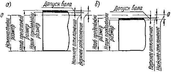
Rice. 76 Limit dimensions and deviations of shaft dimensions
Depending on the nature of the fit, the largest and smallest maximum dimensions of the shaft may be larger (Fig. 76, a) or smaller (Fig. 76, b) its nominal size. In the same way, the largest and smallest limiting dimensions of the hole can be larger (Fig. 77, a) or smaller (Fig. 77, 6) than its nominal size.
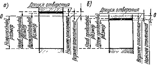
Rice. 77. Limit dimensions and deviations of hole sizes
In addition to the ratios of the maximum and nominal sizes of shafts and holes just listed, other cases are possible.
In Fig. 76 and 77 the letters 00 indicate the so-called zero line. It corresponds to the nominal diameter of the shaft or hole and serves as the starting point for measuring deviations from the nominal size.
Dimensions on drawings
Introduction
In conditions of mass production, it is important to ensure interchangeability identical parts. Interchangeability allows you to replace a part that breaks during operation of the mechanism with a spare one. The new part must exactly match the size and shape of the one being replaced.
The main condition for interchangeability is the manufacture of parts with a certain accuracy. The accuracy of manufacturing a part should be indicated on the drawings by the permissible maximum deviations.
The surfaces along which parts are connected are called mating . In the connection of two parts that fit into one another, a distinction is made between the female surface and the male surface. The most common connections in mechanical engineering are connections with cylindrical and flat parallel surfaces. In a cylindrical connection, the surface of the hole covers the surface of the shaft (Fig. 1, a). The covering surface is usually called hole , covering – shaft . These same terms hole And shaft conditionally used to designate any other non-cylindrical male and female surfaces (Fig. 1, b).
Rice. 1. Explanation of terms hole And shaft
Landing
Any operation of assembling parts involves the need to connect or, as they say, plant one detail to another. Hence the expression adopted in technology landing to indicate the nature of the connection of parts.
Under the term landing understand the degree of mobility of the assembled parts relative to each other.
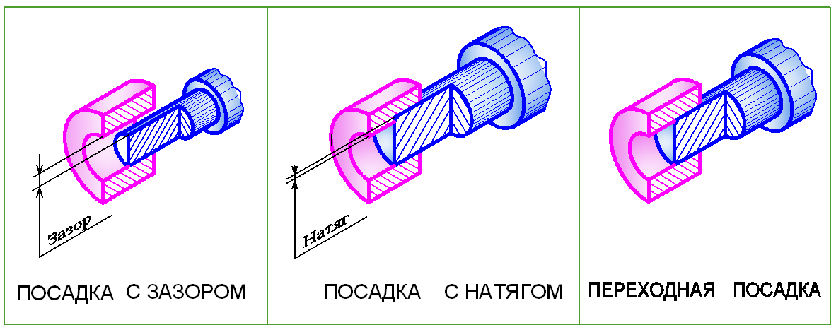
There are three groups of landings: with clearance, with interference and transitional.
Landings with clearance
Gap the difference between the sizes of the hole D and the shaft d is called if the size of the hole is larger than the size of the shaft (Fig. 2, a). The gap ensures free movement (rotation) of the shaft in the hole. Therefore, landings with a gap are called movable landings. The larger the gap, the greater the freedom of movement. However, in reality, when designing machines with movable landings, a gap is chosen that will minimize the coefficient of friction between the shaft and the hole.
Rice. 2. Landings
Preference fits
For these fits, the hole diameter D is less than the shaft diameter d (Fig. 2, b). In reality, this connection can be made under pressure, when the female part (hole) is heated and (or) the male part (shaft) is cooled.
Preference landings are called fixed landings , since mutual movement of the connected parts is excluded.
Transitional landings
These fits are called transitional because before assembling the shaft and hole it is impossible to say what will happen in the connection - a gap or an interference fit. This means that in transitional fits the hole diameter D can be smaller, larger or equal to the shaft diameter d (Fig. 2, c).
Size tolerance. Tolerance field. Quality of accuracy Basic concepts
Dimensions on part drawings quantify the size of the geometric shapes of a part. Dimensions are divided into nominal, actual and limiting (Fig. 3).
Nominal size - this is the main calculated size of the part, taking into account its purpose and the required accuracy.
Nominal connection size – this is the common (same) size for the hole and shaft that make up the connection. The nominal dimensions of parts and connections are not chosen arbitrarily, but according to GOST 6636-69 “Normal linear dimensions”. In real production, when manufacturing parts, nominal dimensions cannot be maintained and therefore the concept of actual dimensions has been introduced.
Actual size – this is the size obtained during the manufacture of the part. It always differs from the nominal value up or down. The permissible limits of these deviations are established by means of maximum dimensions.
Limit dimensions name two boundary values between which the actual size must lie. The larger of these values is called largest size limit, less – smallest size limit. In everyday practice, on drawings of parts, it is customary to indicate maximum dimensions by means of deviations from the nominal.
Maximum deviation is the algebraic difference between the maximum and nominal sizes. There are upper and lower deviations. Upper deviation is the algebraic difference between the largest limit size and the nominal size. Lower deviation is the algebraic difference between the smallest limit size and the nominal size.
The nominal size serves as the starting point for deviations. Deviations can be positive, negative or equal to zero. In tables of standards, deviations are indicated in micrometers (µm). In drawings, deviations are usually indicated in millimeters (mm).
Actual deviation is the algebraic difference between the real and nominal sizes. The part is considered acceptable if the actual deviation of the size being checked is between the upper and lower deviations.
Size tolerance is the difference between the largest and smallest limit sizes or the absolute value of the algebraic difference between the upper and lower deviations.
Under quality understand a set of tolerances that vary depending on the nominal size. 19 qualifications have been established, corresponding to different levels of precision in manufacturing a part. For each qualification, a series of tolerance fields have been constructed
Tolerance field – this is a field limited by upper and lower deviations. All tolerance fields for holes and shafts are indicated by letters of the Latin alphabet: for holes - in capital letters (H, K, F, G, etc.); for shafts - lowercase (h, k, f, g, etc.).
Rice. 3. Explanations of terms