
As indicated by the beam in the drawing. Drawings of technological metal structures. Symbols of welds
Images in the drawing, depending on their content, are divided into views, sections and sections.
2.2.1 Types. The rules for depicting objects in drawings are established by GOST 2.305–68.
A view is an image of the visible part of the product surface facing the observer. To reduce the number of images in views, it is allowed to show the necessary invisible parts of the object surface using dashed lines. This allows us to consider that the view is a projection of an object on the corresponding plane (for example, the main view is a frontal projection, etc.). According to the content, the types are divided into basic, additional
nye and local.
The main types called those that are obtained by projecting the product onto six main projection planes (Figure 30).
Figure 30 - Main views
The following names of the main views are set: front view (main view); top view (under the main view); left view (on the right side of the main view); right view (on the left side of the main view); bottom view (above the main view) ; rear view (on the right side of the left view or on the left side of the right view).
The main view (front view) is the main view of the object on the frontal plane of the projections, which gives the most complete picture of its shape and size. To obtain such an image, it is necessary to properly position the object relative to the frontal plane of the projections. The rest of the main types are located relative to the main species.
The number of views in the drawing should be the smallest, but sufficient to fully reveal the shape and size of the object. To reduce the number of views on them, it is allowed to show the invisible parts of the object's surface with dashed lines.

The main views are usually located in a projection connection, then no inscriptions explaining the name of the species are made. If they are not in projection connection with the main view, then the direction of projection should be indicated by an arrow near the corresponding image. The same uppercase letter should be applied above the arrow and above the resulting image.
Additional types are called images of the visible part of the surface of an object on planes that are not parallel to any of the main projection planes (Figure 31). They are used when it is impossible to show any part of the object in the main views without distorting the shape and size. To obtain undistorted images inclined to the main planes, the elements of the product are projected onto an additional plane parallel to them and aligned with the plane of the drawing, that is, the method of replacing the projection planes is used.
Figure 31 - Additional views
The additional view should be marked in the drawing with a capital letter, and the product image associated with the additional view should have an arrow indicating the direction of view, with the corresponding letter designation (see Figure 31). In the event that the additional view is located in direct projection connection with the corresponding image, no inscriptions are applied above it and the direction of view is not indicated with an arrow.
An additional view is allowed to unfold while maintaining the position adopted for the product in the main view. In this case, the type designation should be
A local view is an image of a separate limited area of the surface of an object (Figure 32). Local view can be limited by the clipping line and should be marked on the drawing like an additional view.

Figure 32 - Local view
2.2.2 Sections. Incision - an image of an object mentally dissected by one or more planes. The section shows what is obtained in the secant plane and what is behind it ( figure 33 ). Such an image is built on a plane parallel to the secant plane.
Depending on the position of the secant plane, the cuts are divided into horizontal cuts (the secant plane is parallel
plane H), vertical (the cutting plane is perpendicular to the plane H), inclined (the cutting plane makes an angle with the plane H, which is different from the right one). Vertical sections can be frontal (the secant plane is parallel to the frontal plane of the projections V) or profile (the secant plane is parallel to the profile plane of the projections W).
Depending on the number of secant planes, the cuts are divided into simple (one secant plane) and complex (several secant planes).
Figure 33 - An example of a frontal section
Depending on the position of the secant planes, complex cuts are divided into stepped (Figure 34), when the secant planes are parallel, broken, when the secant planes intersect with each other (Figure 35).
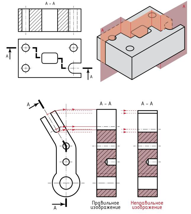
Figure 34 - Stepped section
Figure 35 - Broken section
The position of the cutting plane is indicated in the drawing with a section line (see Figures 33-35). An open line is used to draw the section line (see table 3). With a complex section, strokes are also drawn at the intersection of the secant planes with each other (see Figure 34). On the initial and final strokes, arrows are placed perpendicularly, at a distance of 2 ... 3 mm from their ends, indicating the direction of the gaze. In the outer corner formed by the arrow and the continuation of the stroke, they put the same uppercase Russian letter.
The incision is always indicated by two letters separated by a dash, for example "A - A", "B - B", etc. The use of letters Y, O, b, L, L is not allowed. When the cut is rotated to the position adopted for the product on the main image, the designation takes the form "D - D".
The strokes of the cut line should not intersect the contour of the product image. When the secant plane coincides with the plane of symmetry of the product, and the corresponding images are located in a projection relationship and are not separated by other images, for horizontal, frontal and profile cuts, the position of the secant plane is not marked
and the section is not marked with an inscription. The local incision serves to determine
changing the shape of the object only in a separate limited place. It is indicated in the corresponding view, as shown in Fig.
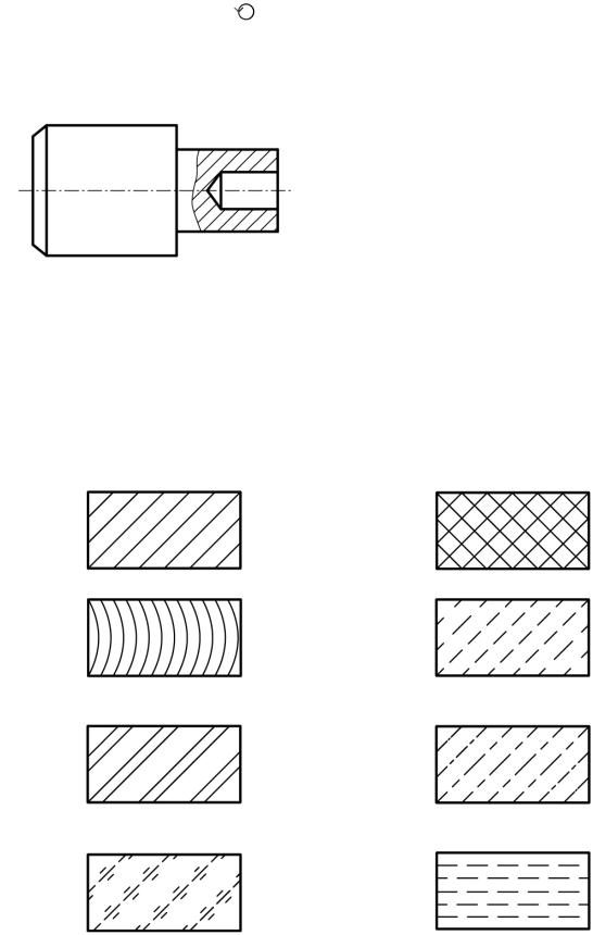
The walls of the product cut by the cutting plane must be hatched in accordance with the material of the part. The rules for applying shading are determined by GOST 2.306–68. Graphic designation of materials depending on their type are given in Table 5.
Table 5 - Graphic designations of materials in sections and sections
Metals and hard alloys | Non-metallic materials, including |
fibrous monolithic and plate (press- |
|
bathrooms), except for those indicated in the table |
|
Wood | Natural stone |
Ceramics and silicate materials | |
for masonry | |
Glass and other translucent | Liquids |
materials | |

Those parts of the object that are located behind the plane of the cut are not shaded.
Inclined parallel hatch lines should be drawn at an angle of 45 ° to the image contour line or to its axis (for example, in the case of an oval), or to the lines of the drawing frame. If the hatch lines, reduced to the line of the drawing frame at an angle of 45 °, coincide with the contour lines or center lines, then instead of the angle of 45 °, an angle of 30 ° or 60 ° should be taken.
Hatch lines should be applied with a slope to the left or right, but in the same direction on all sections related to the same part.
The distance between parallel straight lines of hatching should be the same for all sections of a given part made on the same scale. It is selected depending on the area of the hatching and the need to diversify the hatching of adjacent sections. As a rule, this distance is chosen in the range from 1 to 10 mm.
In adjacent sections with hatching of the same slope and direction, the distance between the hatching lines should be changed (Figure 37) or shifted
these lines are in one section with respect to |
|
the other, without changing the angle of their inclination. |
|
When hatching in a cage for adjacent |
|
sections of two parts, the distance between the lines |
|
shading lines in each section should |
|
be different. |
|
On the cuts there are thin walls, the ribs are stiff |
|
bones, knitting needles show unshaded |
|
Figure 37 - Hatching | if the cutting plane passes |
assembly units | along the axis or long side of the element de- |
hoist (Figure 38). |
In an image that is a connection of a view and a section, it is recommended that the dimensions that determine the outer shape of the part be placed from the side of the view, and the inner one - from the side of the section. In this case, the dimension lines related to the internal elements of the part are drawn with a break and the break of the dimension line is made beyond the axis of symmetry.
Figure 38 - Image of sections of thin walls and stiffeners
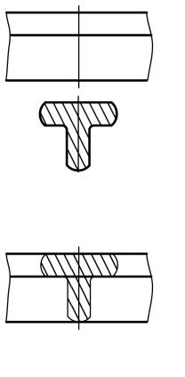
Figure 39 - Extended section
Figure 40 - Superimposed section
2.2.3 Sections. Section - an image of a figure obtained by mentally dissecting an object by a plane (or several planes). The section shows only what is obtained directly in the cutting plane.
Sections that are not part of the section are divided into removed (Figure 39) and superimposed (Figure 40).
Remote section called the section,
located outside the outline of the object view in the drawing. They are allowed to be located in the gap between parts of the same type. Extended sections are preferable to superimposed sections, which darken the drawing. The contour of the extended section, as well as the section that is part of the section, is depicted by solid main lines.
Superimposed section called the section,
located directly on the object view. The contour of the superimposed section is depicted with solid thin lines, and the contour of the image
at the location of the superimposed section, do not interrupt.
With a symmetrical section figure, if the axis of symmetry of the section coincides with the position of the secant plane, the extended section can be positioned so that its axis of symmetry is a continuation of the projection of the secant plane (Figure 41, a). In this case, the position of the secant plane is indicated by a thin dash-dot line without designation with letters and arrows, and the section line is not drawn. The same applies to a symmetrical superimposed section (Figure 41, b). Figure 41, in a symmetrical section, is located at the gap between parts of the same type.
In all other cases, an open line is used, indicating the direction of gaze with arrows, designating it with the same capital letters of the Russian alphabet. The section is accompanied by an inscription of the "A - A" type (Figure 41, d). Sizes of letters, size of arrows and other data are the same as for cuts.
The construction and location of the section must correspond to the direction indicated by the arrows. It is allowed to place a section anywhere in the drawing field.
For asymmetric sections located in a gap (Figure 41, e) or superimposed (Figure 41, e), the section line is drawn with arrows, but they are not indicated by letters.

a - taken out section; b, f - superimposed section; в - symmetrical section;
G - accompanying inscription for the section; d - asymmetrical section
Figure 41 - Sectional views
2.2.4 Dimensions. GOST 2.307-68 establishes the rules for applying dimensions
and marginal deviations on design documents.
In the drawing, it is necessary to apply the actual dimensions of the object, regardless of the scale of the image. The total number of sizes should be minimal, but sufficient to represent and manufacture the object. Each dimension is indicated on the drawing only once.
The dimensions in the drawings must be indicated dimensional numbers and dimension lines preferably outside the outline of the image.
When drawing the size of a rectilinear segment, the dimension line is drawn parallel to this segment, and the extension lines are perpendicular to the dimensional ones. When applying the size of the angle, the dimension line is drawn in the form of an arc with a center at its apex, and extension lines are drawn radially.
Dimensional numbers of linear dimensions in the drawings are indicated in millimeters without designation of the unit of measurement. In the case when the size is not a multiple of a millimeter, decimal fractions are allowed. Dimensional numbers of angular dimensions are indicated in degrees, minutes and seconds with designation of units of measurement (examples: 15 °; 35 ° 15 "; 0 ° 0" 19 "").
The dimension line at both ends is limited by arrows that abut the extension, centerline or contour lines (see Figure 24). Dimension numbers are applied above the dimension line as close to its middle as possible. The extension lines should extend beyond the ends of the arrows of the dimension line by 1 ... 5 mm.
Avoid crossing dimension and extension lines. Also, it is not allowed to use contour lines and center lines as dimensions.
The minimum distance between pa-
parallel | dimensional | ||||||||||||
should be 7 mm, and between the dimensional |
|||||||||||||
(Figure 42). | |||||||||||||
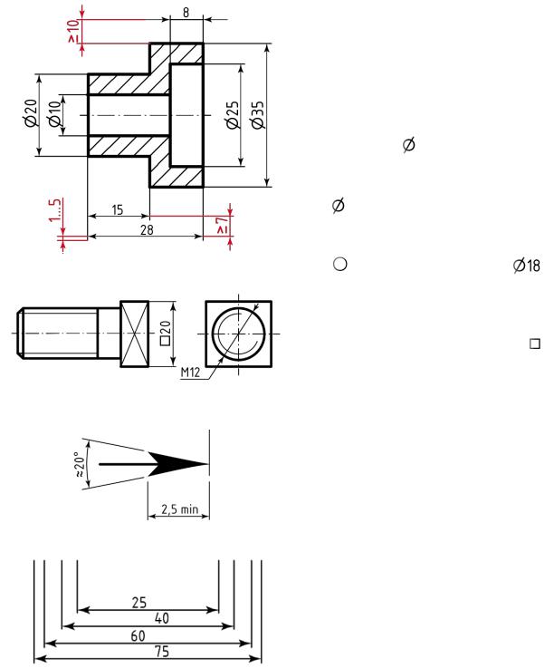
When specifying the size of the diameter (in |
|||||||||||||
all cases) before the dimension number |
|||||||||||||
put a sign | (see Figure 42), and |
||||||||||||
the measure of the radius is the sign R. Before dimensional |
|||||||||||||
the number of the diameter of the sphere is also applied |
|||||||||||||
or R. If the drawing is difficult to identify |
|||||||||||||
separate the sphere from other surfaces, then |
|||||||||||||
dimensional | indicated |
||||||||||||
Figure 42 - Dimensioning rules | or the inscription "Sphere | ||||||||||||
meter sign of the sphere is equal to size size- |
|||||||||||||
numbers. | |||||||||||||
The dimensions of the square are applied, as shown |
|||||||||||||
shown in Figure 43. Sign height | |||||||||||||
be equal to height dimensional numbers. |
|||||||||||||
Figure 43 - Application example | Arrow element sizes size- |
||||||||||||
lines are chosen depending on |
|||||||||||||
the size of the square |
|||||||||||||
the thickness of the lines of the visible contour and |
|||||||||||||
draw them approximately the same |
|||||||||||||
in all drawings. Arrow shape and |
|||||||||||||
the approximate ratio of its elements |
|||||||||||||
shown in Figure 44. | |||||||||||||
When applying several parallel |
|||||||||||||
Figure 44 - Shape and size of the arrow | dimension lines at a small distance |
||||||||||||
standing apart dimensional numbers above |
|||||||||||||
matte order (Figure 45). | |||||||||||||
Dimensional numbers of linear dimensions |
|||||||||||||
at different slopes of dimensional lines |
|||||||||||||
are shown in Figure 46. If necessary If there is not enough space above the dimension line to write the dimension number, then the dimension number is applied in accordance with Figure 48. If there is no space for drawing arrows, then they are placed as shown in Figure 49. The method of applying the dimension number at different positions of the dimension lines (arrows) in the drawing is determined by the greatest readability. When drawing several radii from one center, the dimension lines of any two radii should not be located on one straight line (Figure 50). If the centers of several radii coincide, their dimension lines may not be brought to the center, except for the extreme ones. The dimensions of the radii of the outer fillets are applied as shown in Figure 51, a; internal - in Figure 51, b. Figure 49 - Example of applying dimensions in case there is not enough space for drawing arrows
Figure 50 - An example of applying the dimensions of the radius Figure 51 - An example of applying the dimensions of the radii of the outer and inner fillets If the radii of rounding, bends and others are the same throughout the drawing or any radius is predominant, instead of drawing their dimensions, it is recommended to make an entry in the technical requirements above the main inscription of the type: "Radii of rounding 5 mm", "Unspecified radii of 10 mm", etc. NS. The dimensions of the chamfers are applied at an angle of 45 °, as shown in Figure 52, a, b. If the angle of the chamfer is not equal to 45 °, then its designation is carried out according to the general rules - linear and angular dimensions (Figure 52, c) or two linear dimensions (Figure 52, d). The dimensions of several identical elements of the product (chamfers, holes) are applied once, indicating the number of these elements on the shelf of the leader line (Figure 53, a). It is allowed to indicate the number of elements, as shown in Figure 53, b. Figure 52 - Example of applying the dimensions of chamfers Figure 53 - An example of applying dimensions of several identical elements of the product
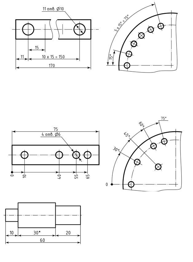
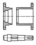
When applying dimensions that determine the distance between equally spaced identical elements (for example, holes), it is recommended to apply the size between adjacent elements and the size between the extreme elements in the form of the inscription "m x n = k", where m, n and k are dimension numbers (Figure 54). Figure 54 - An example of applying the dimensions of a chain of identical elements With a large number of dimensions plotted from a common base, it is allowed to apply linear and angular dimensions, as shown in Figure 55. At the same time, a general dimension line is drawn from the "0" mark and dimension numbers are applied in the direction of the extension lines at their ends. Figure 55 - An example of applying a chain of dimensions from a common base Figure 56 - Example of applying reference dimensions The drawings apply reference dimensions... Reference dimensions are dimensions that are not subject to execution according to this drawing, they are indicated for greater ease of use (Figure 56). Reference dimensions are indicated by "*", and in the technical requirements above the title block write "* Dimensions for reference". | |||||||||||||

General Provisions
1. Working drawings are developed for all parts (except purchased and standard) that make up the product. A drawing of each part is performed on a separate sheet. The main inscription is placed on sheets of a standard format: on A4 format - along the short side; on others, mainly along the long side of the leaf. In the columns of the title block, the following is given:
· Name of the part, for example: "Cogwheel";
· Designation of the drawing of the part, for example: 5ТМ1д.2.18.10 11;
· Designation according to the standard of the material of the part, for example: Steel 40ХН GOST 4543 - 71. If the designation includes the abbreviated name of the material ("St", "SCh", "Br"), then the full name ("Steel", "Gray cast iron", "Bronze") do not indicate, for example: "StZ GOST 380 - 2005". If a part is to be made of a high-quality material of a certain profile and size, then the material of such a part is recorded in accordance with the designation assigned to it in the standard for the product mix, for example:
1. The detail is shown in the drawing in the position in which it is installed on the machine, in particular, the axis of the detail - the body of revolution (shaft, gear wheel, glass, etc.) is placed parallel to the main inscription.
Rice. 4.3. Part location in the drawing
3. Image of a part - bodies of revolution are placed on the drawing to the right with the side more laborious for turning (Fig. 4.3).
4. It is not allowed to place technological instructions on the drawing of the part. As an exception, you can specify joint processing, lapping, bending, flaring. Due to this center holes, which are technological bases, are not shown in the drawings of parts and no instructions are placed in the technical requirements(except for holes with metric thread, see appendix 33)
5. If the machining of holes for screws, pins and other fasteners is performed during assembly, then these holes are not shown in the drawing of the details and no instructions are given in the technical requirements. All the necessary information is given on the drawing of the assembly unit.
Dimensioning
1. The drawing must be set minimal number of sizes, but sufficient for the manufacture and control of the part.
2. Each dimension should be shown in the drawing only one once.
3. Dimensions related to one structural element should be grouped in one place (Fig. 4.4).

Rice. 4.4. Dimensioning

Rice. 4.5. Chamfer and groove dimensions
4. It is not allowed to include the width of the chamfers and grooves in the overall chain of dimensions (Fig. 4.5).
5. The dimensions of the elements of the parts to be processed jointly are enclosed in square brackets and in the technical requirements they write “Processing in size in square brackets together with children. N. "
6. The dimensions given in the drawings of the parts are conventionally divided:
· on functional, defining quality indicators of the product: assembly dimensions dimensional chains, conjugate dimensions, diameters of shaft seats for gears, worm wheels, diameters of screws on bearing caps;
· on free(dimensions of non-mating surfaces);
· For reference.
The basic principle of dimensioning in part drawings is as follows. Functional dimensions set on the drawings of parts, taking them from the drawing of the assembly unit (gearbox, gearbox) and from the dimensional chain diagrams. Free sizes set taking into account the manufacturing technology and ease of control. Reference dimensions are not subject to execution according to this drawing. They are indicated for greater convenience in using the drawing, during the manufacture of the part, they are not controlled. Reference dimensions are marked with an asterisk and in the technical requirements they make an entry of the type: "* Dimensions for reference."
Limit deviations of dimensions
For all dimensions plotted on the drawing, indicate the maximum deviations in millimeters. It is allowed not to indicate the maximum deviations on the dimensions that determine the zones of different roughness and different accuracy of the same surface, heat treatment zone, coating, knurling. In these cases, the sign "" is applied directly to such sizes (Fig. 4.6, a). If necessary, instead of the sign "" for such sizes, set the maximum deviations (Fig. 4.6, b).

Rice. 4.6. Application of limit deviations of dimensions
2. Limit deviations of multiply repeating sizes of relatively low accuracy (from the 12th grade and coarser) are not applied to the image of the part, but are indicated in the technical requirements by a general record of the type:
"Unspecified limit deviations of dimensions: holes + H14, shafts -h14, others ± 1T14 / 2".
Here under "Shaft" understand any external, including non-cylindrical, elements of the part (for example, protrusions), and under "Hole" - l Any internal (for example, grooves) dimensions.
3. Limit deviations of linear dimensions are indicated in one of the following three ways:
· Symbols of tolerance fields, for example: 63H7;
· Numerical values of maximum deviations, for example: 64 +0, '030;
· Symbols of tolerance fields with indication on the right in brackets the value of maximum deviation, for example: 18P8.
First the method is recommended to be used with nominal sizes included in a series of standard numbers, second - at non-standard numbers nominal sizes and third - with standard numbers, but not recommended tolerance bands.
4. Limit deviations free sizes stipulated in the technical requirements by a record similar to the record for low-precision dimensions.
Shape tolerances and surface positioning tolerances
When processing parts, errors arise not only in linear dimensions, but also in geometric shapes, as well as errors in the relative location of these, surfaces and structural elements of parts.
The first group of accuracy requirements is associated with the installation of rolling bearings (GOST3325 - 85). It is important for rolling bearings that the raceways of the bearing rings are not distorted. The relative misalignment of the outer and inner rings of bearings increases the resistance to rotation of the shafts and energy losses, and reduces the bearing life. The misalignment of the rings can be caused by: deviations from the alignment of the shaft and housing seating surfaces; deviations from the perpendicularity of the base ends of the shaft and housing; deformation of the shaft and housing in the operating unit.
To limit the listed deviations, the tolerances of the location of the shaft and housing seating surfaces are specified in the drawings.
Table 4.2 Symbols for the tolerances of the shape and location of surfaces
|
Roundness |
|
|
Cylindricity |
|
|
Coaxiality |
|
|
Parallelism |
|
|
Perpendicularity |
|
|
Radial runout |
|
|
Symmetry |
|
|
Positional |
The second group of accuracy requirements imposed on parts is associated with ensuring the norms of kinematic accuracy and the norms of contact of gear and worm gears. Achievement the required transmission accuracy depends on the accuracy of the location of the seating surfaces and base ends of the shafts, as well as the bores and base ends
The third group of requirements is associated with the need to limit the possible imbalance of parts. The permissible unbalance values are determined by GOST 22061 - 76, depending on the type of product and its operating conditions. In this regard, in the drawings it is convenient to present to individual surfaces of parts requirements in the form of alignment tolerances.
Reference axes and surfaces designate in the drawings in accordance with GOST 2.308 - 79 an equilateral blackened triangle connected to a frame in which the designation of the base is written in a capital letter
Tolerances of the shape and location of surfaces indicate on the drawing by symbols - graphic signs (table 4.2), which are written in a frame divided into two or three parts. In the first part, a graphic tolerance mark is placed, in the second - its numerical value and in the third - the designation of the base, relative to which the tolerance is set.
The following rules have been established (GOST 2.308 - 79) for drawing on the drawings of details of conventional designations of bases, shape and location tolerances:
If the base is surface, then the blackened triangle is located at a sufficient distance from the end of the dimension line (Figure 4.7, a);
4.7. Symbols of bases, tolerances of form and location
If the base is axis or plane of symmetry, then the blackened triangle is located at the end of the dimension line (Figure 4.7, b ). Sometimes it is more convenient, so as not to obscure the drawing, to show the base in a section. In this case, the dimension line without specifying the size is repeated;
If there is no need to assign a base, an arrow is used instead of the blackened triangle (Figure 4.7, c):
· If the tolerance refers to the surface, and not to the axis of the element, then the arrow of the connecting line is located at a sufficient distance from the end of the dimension line (Figure 4.7, d - designation of the cylindrical tolerance);
· if tolerance include to the axis or planes of symmetry, then the end of the connecting line must coincide with the continuation of the dimension line (Figure 4.7, d – alignment tolerance designation).
Surface roughness
Of the roughness parameters established by GOST 2789 - 73, the following are most often used in mechanical engineering:
Rа is the arithmetic mean deviation of the profile, μm (the main of the height parameters of roughness; assigned to all treated surfaces);
Rz - the height of the irregularities of the profile, μm (determined by five measurements of the heights of the irregularities; assigned to the surfaces obtained by casting, forging, embossing).
To indicate the roughness of surfaces in the drawings, signs are used (Figure 4.14).
The design of the signs is shown in Fig. 4.8. The height h is equal to the height of the dimensional numbers in the drawing, the height H = (1.5 ... 3.0) h - depending on the volume of the record.

Rice. 4.8. Surface treatment designation

Rice. 4.9. Prevailing roughness designation
If the designer does not establish the type of surface treatment, then the sign according to Fig. 4.8, a. This designation is preferred. If it is required that the surface was formed by necessarily removing a layer of material, for example, turning, grinding, polishing, etc., use the sign in Fig. 4.8, b. If it is important that the surface is formed without removing the layer of material, use the sign in Fig. 4.8, in .
The designation of the prevailing roughness is shown in the upper right corner of the drawing field (Fig. 4.9, a). If the prevailing number of surfaces is not processed according to this drawing, then their roughness is shown in the upper right corner of the drawing field according to Fig. 4.9, b). Numerical values of the roughness parameter Rа can be taken according to the table. 4.3.
Table 4.3 Roughness parameters
|
Surface type |
|
|
Seating surfaces of shafts and housings made of steel for rolling bearings of accuracy class 0 at: d or D up to 80 mm d or D St. 80 mm Seating surfaces of cast iron housings for rolling bearings with accuracy 0 at: Shaft surfaces for rubber seals Grooves, chamfers, fillet radii on shafts The ends of the hubs of gear, worm wheels, based on the butt of the shoulders fishing, with the ratio of the length of the hole in the hub to its diameter: Working surfaces of the teeth gear wheels external gear: with module< 5 мм with module> 5 mm Working surfaces of cylindrical worm turns The surfaces of the projections of the teeth of wheels, turns of worms, teeth of chain sprockets Working surface of belt pulleys The working surface of the teeth of the chain sprockets Hole surfaces for bolts, screws, studs Support surfaces for the heads of bolts, screws, nuts |
Roughness of surfaces not listed in the table. 4.3 can be determined by the formula:
where t is the size tolerance (or according to the working drawings of the parts given in the manual).
Heat treatment designation
The following rules have been established for applying instructions on thermal and chemical-thermal treatment on the drawings, which ensure the obtaining of the necessary properties of the material of the part. If the entire part is subjected to heat treatment of the same type, then in the technical requirements of the drawing, the required indicators of material properties are given with a record of the type:

Rice. 4.10. Heat treatment designation
a) 235 ... 265 HB or 250 ± 15 HB;
b) 44 ... 50 HRC E or 47 + 3 HRC E;
c) HDTV h1.6 ... 2.0 mm, 50 ... 56 NRS E,
or HDTV h1.8 ± 0.2 mm, 53 ± 3 HRC E
(with the letter "h" the depth of processing is indicated);
d) cement h 0.8 ... 1.2 mm
or h (1.0 ± 0.2) mm); 56 ... 62 НRS Э
or (59 ± 3) HRC E.
If a separate section of the part is subjected to heat treatment, then it is circled in the drawing with a thickened dash-dot line, and indicators of material properties are applied on the shelf of the leader line (Figure 4.10, a). If the entire part is subjected to one type of heat treatment, and some of its parts to another or are left untreated, an entry is made in the technical requirements by the type:
· "269 ... 302 НВ, except for a place specially marked" (Fig. 4.10, a);
· "40 ... 45 NRS E, except for surface A" (Figure 4.10, b).
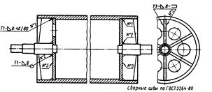
Weld designation
Drawings of welded parts are drawn up as drawings of assembly units. Elements of the welded part in cuts and sections are hatched in different directions (Figure 4.11, a). If the welded part is depicted assembled with other parts, then all its elements are hatched in one direction (Figure 4.11, b). Welded seams in the drawings of parts are depicted and designated in accordance with GOST 2.312 - 72. Visible seams are depicted as solid, and invisible - in dashed lines.
Rice. 4.11. Welded parts
The seam symbol is applied:
· on the shelf leader lines drawn from the seam image from the front side (Fig. 4.12, a);
· under the shelf leader lines drawn from the image of the seam on the reverse side (Fig. 4.12, b).
The symbol of the welds should contain, in the order shown by rectangles 1 - 5 (Figure 4.12), the following:
1. Auxiliary signs, for example:
2 Designation of the standard for types and structural elements of welded joints:
a) GOST 5264 - 80 - main types and structural elements of seams made by manual arc welding;

Rice. 4.12. Weld designation
b) GOST 8713 - 79 - main types and structural elements of seams made by automatic or semi-automatic submerged arc welding;
c) GOST 15878 - 79 - resistance welding joints.
3. Designation of a seam consisting of a letter indicating the type of joint and a number indicating the form of edge preparation (with flanging, without flanging), for example: C8 - butt seam, U4 - corner, TZ - tee, H2 - overlap joints.
4. Sign and size of the leg leg (only for fillet welds).
5. Auxiliary signs: / - intermittent or point seam with a chain arrangement; - the seam is intermittent or punctate with a staggered arrangement.
The designation of the same seams is applied only in one of the images. Leader lines with shelves are drawn from the images of the remaining seams. All identical seams are assigned one serial number (Figure 4.13), which is applied:
· On a leader line with a shelf with an applied seam designation;
· On the shelf of a leader line drawn from the image of a visible seam that does not have a designation;
Rice. 4.13. Identification of identical welds
· Under the shelf of the leader line drawn from the image of an invisible seam that does not have a designation.
Location on the drawing of the technical information part
For the convenience of reading the drawing, all the information required for manufacturing or should be organized into the following system.
On the drawings of parts - bodies of revolution (shafts, gear shafts, worms, wheels, glasses, bearing caps) should be located (Fig.4.14):
· Axial linear dimensions - under the image of the part at the smallest possible (2 - 3) number of levels;
· Legend of bases - under the image of the part;
· Symbols of tolerances of shape and location - above the image of the part at one or two levels;
· Legend of roughness parameters - on the upper parts of the image of parts, and on the end surfaces - under the image of the part. In both cases, the roughness symbols are located in the immediate vicinity of the dimension line;
· Leader line shelves that indicate surfaces to heat treat coatings above the part image.
Technical requirements are located above the main inscription (Fig. 4.14), with a lack of space - to the left of the main inscription. Technical requirements are recorded in the following order:
1. Requirements for the material, workpiece, heat treatment and material properties of the finished part.
2. Sizing instructions (dimensions for reference, etc.).
3. Limit deviations of dimensions (unspecified maximum deviations, etc.)
4. Tolerances of the shape and relative position of surfaces for which in GOST 2.308 - 79 there are no conventional graphic symbols.
5. Requirements for surface quality (instructions for finishing, coating, roughness).
For dimensions and maximum deviations given in the technical requirements, be sure to indicate the units of values. The title "Technical Requirements" is not written.
GOST 2.308-79
Group T52
INTERSTATE STANDARD
Unified system for design documentation
INDICATION ON THE TOLERANCES FOR THE SHAPE AND POSITION OF SURFACES
Unified system for design documentation. Representation of limits of forms and surface lay-out on drawings
ISS 01.080.30
Date of introduction 1980-01-01
By the decree of the USSR State Committee for Standards of January 4, 1979 N 31, the date of introduction was established 01.01.80
REPLACE GOST 2.308-68
EDITION (August 2007) with Amendment No. 1, approved in August 1984 (IUS 12-84).
This standard establishes the rules for indicating the tolerances of the shape and location of surfaces on the drawings of products of all industries.
Terms and definitions of tolerances of the shape and location of surfaces - in accordance with GOST 24642-81.
The numerical values of the tolerances of the shape and location of surfaces are in accordance with GOST 24643-81.
The standard is fully consistent with ST SEV 368-76.
1. GENERAL REQUIREMENTS
1. GENERAL REQUIREMENTS
1.1. The tolerances of the shape and location of surfaces are indicated in the drawings with symbols.
The type of tolerance of the shape and location of surfaces should be indicated in the drawing by the signs (graphic symbols) given in the table.
Tolerance group | Type of admission | |
Shape tolerance | Straightness tolerance | |
Flatness tolerance | ||
Roundness tolerance | ||
Cylindrical tolerance | ||
Longitudinal section profile tolerance | ||
Location tolerance | Parallelism tolerance | |
Squareness tolerance | ||
Tilt tolerance | ||
Alignment tolerance | ||
Symmetry tolerance | ||
Positional tolerance | ||
Axis intersection tolerance | ||
Overall shape and location tolerances | Radial runout tolerance | |
Full radial runout tolerance | ||
Full face runout tolerance | ||
Tolerance of the shape of a given profile | ||
Tolerance of the shape of a given surface |
The shapes and sizes of signs are given in Appendix 1.
Examples of indications on the drawings of the tolerances of the shape and location of surfaces are given in Appendix 2.
Note. The total tolerances of the shape and location of surfaces, for which separate graphic signs are not installed, are designated by signs of composite tolerances in the following sequence: location tolerance sign, shape tolerance sign.
For example:
- sign of the total tolerance of parallelism and flatness;
- sign of the total tolerance of perpendicularity and flatness;
- sign of the total tolerance of inclination and flatness.
1.2. The tolerance of the shape and location of surfaces is allowed to be indicated in text in the technical requirements, as a rule, if there is no sign of the type of tolerance.
1.3. When specifying the tolerance of the shape and location of surfaces in the technical requirements, the text should contain:
type of admission;
an indication of the surface or other element for which the tolerance is set (for this, a letter designation or a constructive name that defines the surface is used);
the numerical value of the tolerance in millimeters;
indication of the bases relative to which the tolerance is set (for location tolerances and total shape and location tolerances);
an indication of the dependent tolerances of the shape or location (where applicable).
1.4. If it is necessary to normalize the tolerances of the shape and location that are not indicated in the drawing by numerical values and are not limited by other tolerances of the shape and location indicated in the drawing, the technical requirements of the drawing must contain a general record of unspecified tolerances of shape and location with reference to GOST 25069-81 * or other documents establishing unspecified form and position tolerances.
________________
* From January 1, 2004, GOST 30893.2-2002 was put into effect (hereinafter).
For example: 1. Unspecified shape and location tolerances - according to GOST 25069-81.
2. Unspecified tolerances of alignment and symmetry - according to GOST 25069-81.
(Introduced additionally, Rev. N 1).
2. APPLICATION OF TOLERANCE LABELS
2.1. With a conventional designation, data on the tolerances of the shape and location of surfaces are indicated in a rectangular frame divided into two or more parts (Fig. 1, 2), in which they place:
in the first - a sign of tolerance according to the table;
in the second - the numerical value of the tolerance in millimeters;
in the third and subsequent ones - the letter designation of the base (s) or the letter designation of the surface with which the location tolerance is associated (clauses 3.7; 3.9).
Damn 2
2.2. Frames should be made with solid thin lines. The height of numbers, letters and signs that fit into the frames should be equal to the font size of the dimension numbers.
A graphic representation of the frame is given in Appendix 1.
2.3. The frame is placed horizontally. If necessary, the vertical arrangement of the frame is allowed.
It is not allowed to cross the frame with any lines.
2.4. The frame is connected to the element to which the tolerance belongs, with a solid thin line ending with an arrow (Fig. 3).
The connecting line can be straight or broken, but the direction of the segment of the connecting line ending with an arrow must correspond to the direction of measurement of the deviation. The connecting line is taken from the frame, as shown in Fig. 4.
In necessary cases, it is allowed:
draw a connecting line from the second (last) part of the frame (Fig. 5a);
end the connecting line with an arrow and from the side of the material of the part (Fig. 5b).
2.5. If the tolerance refers to a surface or its profile, then the frame is connected to the contour line of the surface or its continuation, while the connecting line should not be a continuation of the dimension line (Fig. 6, 7).
Damn 7
2.6. If the tolerance refers to an axis or plane of symmetry, then the connecting line should be a continuation of the dimension line (Figure 8a, b). If there is not enough space, the arrow of the dimension line can be combined with the arrow of the connecting line (Figure 8c).
Damn 8
If the size of the element has already been specified once, then it is not indicated on the other dimension lines of this element used to symbolize the tolerance of the shape and location. Dimension line without dimension should be considered as an integral part of the symbol for the tolerance of the shape or location (Fig. 9).
Damn. 9
2.7. If the tolerance refers to the lateral sides of the thread, then the frame is connected to the image in accordance with Fig. 10a.
If the tolerance refers to the thread axis, then the frame is connected to the image in accordance with Fig. 10b.
2.8. If the tolerance refers to a common axis (plane of symmetry) and it is clear from the drawing for which surfaces this axis (plane of symmetry) is common, then the frame is connected to the axis (plane of symmetry) (Figure 11a, b).
2.9. Before the numerical value of the tolerance, it should be indicated:
symbol, if the circular or cylindrical tolerance field is indicated with a diameter (Fig. 12a);
symbol, if a circular or cylindrical tolerance field is indicated by a radius (Fig. 12b);
symbol, if the tolerances of symmetry, intersection of axes, the shape of a given profile and a given surface, as well as positional tolerances (for the case when the positional tolerance field is limited to two parallel straight lines or planes) are indicated in diametrical terms (Fig. 12c);
a symbol for the same types of tolerances, if they are indicated in radius expression (Fig. 12d);
the word "sphere" and symbols or, if the tolerance field is spherical (Fig. 12d).
Damn 12
2.10. The numerical value of the tolerance of the shape and location of surfaces, indicated in the frame (Fig. 1Za), refers to the entire length of the surface. If the tolerance refers to any part of the surface of a given length (or area), then the specified length (or area) is indicated next to the tolerance and is separated from it by an oblique line (Fig. 13b, c), which should not touch the frame.
If it is necessary to assign a tolerance for the entire length of the surface and for a given length, then the tolerance for a given length is indicated under the tolerance for the entire length (Fig. 13d).
(Modified edition, Amendment N 1).
2.11. If the tolerance should refer to a section located at a certain place of the element, then this section is indicated by a dash-dotted line and limited in size according to Fig. 14.
2.12. If it is necessary to specify a protruding location tolerance field, then the symbol is indicated after the numerical value of the tolerance.
The contour of the protruding part of the normalized element is limited by a thin solid line, and the length and location of the protruding tolerance field are limited by dimensions (Fig. 15).
2.13. Inscriptions supplementing the data given in the tolerance frame should be applied above the frame, below it, or as shown in Fig. 16.
(Modified edition, Amendment N 1).
2.14. If for one element it is necessary to set two different types of tolerance, then it is allowed to combine the frames and arrange them according to Fig. 17 (upper designation).
If for a surface it is required to indicate at the same time the symbol for the tolerance of the shape or location and its letter designation used to normalize another tolerance, then frames with both symbols can be placed side by side on the connecting line (Fig. 17, lower designation).
2.15. Repeating the same or different types tolerances denoted by the same sign, having the same numerical values and referring to the same bases, it is allowed to indicate once in a frame, from which one connecting line departs, then branched out to all normalized elements (Fig. 18).
Damn. 18
2.16. The tolerances of the shape and location of symmetrically located elements on symmetrical parts are indicated once.
3. DESIGNATION OF BASES
3.1. The bases are designated by a blackened triangle, which is connected with a connecting line to the frame. When making drawings with the help of computer output devices, it is allowed not to blacken the triangle denoting the base.
The base triangle should be equilateral, with a height approximately equal to the font size of the dimension numbers.
3.2. If the base is a surface or its profile, then the base of the triangle is placed on the contour line of the surface (Figure 19a) or on its continuation (Figure 19b). In this case, the connecting line should not be a continuation of the dimension line.
3.3. If the base is an axis or plane of symmetry, then the triangle is placed at the end of the dimension line (Fig. 18).
In case of lack of space, the arrow of the dimension line may be replaced with a triangle denoting the base (Fig. 20).
If the base is a common axis (Figure 21a) or a plane of symmetry (Figure 21b) and it is clear from the drawing for which surfaces the axis (plane of symmetry) is common, then the triangle is placed on the axis.
(Modified edition, Amendment N 1).
3.4. If the base is the axis of the center holes, then the inscription "Center axis" is made next to the designation of the base axis (Fig. 22).
It is allowed to designate the base axis of the center holes in accordance with Fig. 23.
3.5. If the base is a certain part of the element, then it is indicated by a dash-dotted line and limited in size in accordance with Fig. 24.
If the base is a certain place of the element, then it must be determined by the dimensions according to Fig. 25.
3.6. If there is no need to select any of the surfaces as a base, then the triangle is replaced with an arrow (Fig. 26).
3.7. If the connection of the frame to the base or other surface to which the deviation of the location belongs is difficult, then the surface is designated by a capital letter inscribed in the third part of the frame. The same letter is inscribed in a frame, which is connected to the designated surface with a line ending in a triangle, if they indicate a base (Fig. 27a), or an arrow, if the indicated surface is not a base (Fig. 27b). In this case, the letter should be placed parallel to the main inscription.
3.8. If the size of the element has already been specified once, then it is not indicated on the other dimension lines of this element used for the reference designation of the base. Dimension line without size should be considered as an integral part of the base symbol (Fig. 28).
3.9. If two or more elements form a combined base and their sequence does not matter (for example, they have a common axis or plane of symmetry), then each element is designated independently and all letters are inscribed in a row in the third part of the frame (Fig. 25, 29).
Damn. 29
3.10. If it is necessary to set the tolerance of the location relative to the set of bases, then the letter designations of the bases are indicated in the independent parts (third and further) of the frame. In this case, the bases are written in descending order of the number of degrees of freedom deprived by them (Fig. 30).
Damn. 30
4. INDICATION OF NOMINAL POSITIONING
4.1. Linear and angular dimensions that determine the nominal location and (or) the nominal shape of the elements limited by the tolerance, when assigning positional tolerance, slope tolerance, tolerance of the shape of a given surface or a given profile, are indicated on the drawings without limit deviations and are enclosed in rectangular frames (Fig. 31 ).
5. DESIGNATION OF DEPENDENT TOLERANCES
5.1. Dependent tolerances of shape and location are indicated by a conventional sign, which is placed:
after the numerical value of the tolerance, if the dependent tolerance is associated with the actual dimensions of the element in question (Figure 32a);
after the letter designation of the base (Fig. 32b) or without the letter designation in the third part of the frame (Fig. 32d), if the dependent tolerance is associated with the actual dimensions of the base element;
after the numerical value of the tolerance and the letter designation of the base (Figure 32c) or without the letter designation (Figure 32d), if the dependent tolerance is associated with the actual dimensions of the considered and base elements.
Damn. 32
5.2. If the location or shape tolerance is not specified as dependent, then it is considered independent.
APPENDIX 1 (mandatory). SHAPE AND SIZE OF SIGNS
ANNEX 1
Mandatory
APPENDIX 2 (reference). EXAMPLES OF DRAWING TOLERANCES FOR THE SHAPE AND POSITION OF SURFACES
APPENDIX 2
Reference
Type of admission | Indication of tolerances of form and location by conventional designation | Explanation |
1. Straightness tolerance | The straightness tolerance of the generatrix of the cone is 0.01 mm. |
|
The straightness tolerance of the hole axis is 0.08 mm (dependent tolerance). |
||
The surface straightness tolerance is 0.25 mm over the entire length and 0.1 mm over a length of 100 mm. |
||
The surface straightness tolerance in the transverse direction is 0.05 mm, in the longitudinal direction is 0.1 mm. |
||
2. Flatness tolerance | The surface flatness tolerance is 0.1 mm. |
|
The flatness tolerance of the surface is 0.1 mm on an area of 100x100 mm. |
||
The flatness tolerance of surfaces relative to the common adjacent plane is 0.1 mm. |
||
The flatness tolerance of each surface is 0.01 mm. |
||
3. Roundness tolerance | Shaft roundness tolerance 0.02 mm. |
|
The roundness tolerance of the cone is 0.02 mm. |
||
4. Tolerance of cylindricity | Shaft cylindricity tolerance 0.04 mm. |
|
Shaft cylindricity tolerance 0.01 mm over a length of 50 mm. Shaft roundness tolerance 0.004 mm. |
||
5. Tolerance of the profile of the longitudinal section | Shaft roundness tolerance 0.01 mm. The tolerance of the profile of the longitudinal section of the shaft is 0.016 mm. |
|
The tolerance of the profile of the longitudinal section of the shaft is 0.1 mm. |
||
6. Parallelism tolerance | The surface parallelism tolerance relative to the surface is 0.02 mm. |
|
The parallelism tolerance of the common adjacent plane of surfaces relative to the surface is 0.1 mm. |
||
The parallelism tolerance of each surface relative to the surface is 0.1 mm. |
||
The tolerance of parallelism to the axis of the hole relative to the base is 0.05 mm. |
||
The tolerance of parallelism of the axes of the holes in the common plane is 0.1 mm. The tolerance of the misalignment of the axes of the holes is 0.2 mm. The base is the axis of the hole. |
||
The tolerance of parallelism to the axis of the hole relative to the axis of the hole is 0.2 mm. |
||
7. Perpendicularity tolerance | The perpendicularity tolerance of the surface relative to the surface is 0.02 mm. |
|
The perpendicularity tolerance of the hole axis relative to the hole axis is 0.06 mm. |
||
The perpendicularity tolerance of the axis of the protrusion relative to the surface is 0.02 mm. |
||
The perpendicularity tolerance of the axis of the protrusion relative to the base is 0.1 mm. |
||
The perpendicularity tolerance of the axis of the protrusion in the transverse direction is 0.2 mm, in the longitudinal direction is 0.1 mm. |
||
The perpendicularity tolerance of the hole axis relative to the surface is 0.1 mm (dependent tolerance). |
||
8. Tilt tolerance | The tolerance of the slope of the surface relative to the surface is 0.08 mm. |
|
The tolerance of the inclination of the axis of the hole relative to the surface is 0.08 mm. |
||
9. Alignment tolerance | Alignment tolerance of the hole relative to the hole 0.08 mm. |
|
The alignment tolerance of two holes relative to their common axis is 0.01 mm (dependent tolerance). |
||
10. Symmetry tolerance | The symmetry tolerance of the groove is 0.05 mm. |
|
The symmetry tolerance of the hole is 0.05 mm (dependent tolerance). The base is the plane of symmetry of the surfaces. |
||
The symmetry tolerance of the hole axis relative to the common plane of symmetry of the grooves is 0.2 mm and relative to the common plane of symmetry of the grooves 0.1 mm. |
||
11. Positional tolerance | Positional tolerance of the hole axis 0.06 mm. |
Symbols and images are used in shipbuilding drafting to make it easier, faster, and easier to read.
All conventions used in the drawings are mainly divided into graphic images, signs and letter designations.
Conditional graphic images are used in working drawings when drawing a structure or its parts on a small scale, when it is impossible to show an exact image. These images are performed on the scale of the drawing, and the conventional signs are performed without observing the scale, but with the preservation of the size of the sign when it is repeated in the same drawing.
Symbols and images are performed in accordance with GOST and industry standards.
Consider the basic conventions and images used in working drawings.
Table 2.1 shows the symbols for sheet, strip and profile metal, and in table. 2.2 some basic designations of the elements and connections of the case are given.
Table 2.1. Symbols of sheets and profiles
* In the design drawings above the line, the dimensions of the wall are indicated, below the line - the belts. In the working drawings, the dimensions of the wall and the band are indicated separately, as for strips.
Table 2.2. Designation of elements and types of connections of metal structures
The dimensions of the profiles are usually determined by the corresponding GOST.
Using the designations in the drawings, you can limit yourself to one projection of the profiles.
Symbols on the drawings of hull structures are given in table. 2.3.
Table 2.3. Abbreviated designation of hull structures in drawings 
At a large scale of the drawing (1: 1, 1: 2 or 1: 5), when the thickness of sheets, strips and profiles in the drawing is more than 2 mm, their sections are shaded. At small scales (1: 10 or less), when the thickness of the details is insufficient for shading (less than 2 mm), the sections are shaded with a pencil, and on tracing paper they are filled in with ink.
The image and conventional designation of welds in the drawings is made in accordance with GOST 2.312-72. Various types of welds are used in shipbuilding, which are defined by the following standards:
GOST 5264-69 - manual electric arc welding.
GOST 11533-75 - automatic and semi-automatic submerged arc welding.
GOST 14771-76 - gas-shielded electric arc welding.
GOST 8713-70 - automatic and semi-automatic submerged arc welding.
GOST 14806-69 - arc welding of aluminum and aluminum alloys.
GOST 15878-79 - welded joints made by contact electric welding.
There are also industry standards that provide requirements for the shipbuilding industry.
If the structural elements of the seams used in the drawing differ from those indicated in the standards, they are specially specified in the drawing or technical conditions for the manufacture of the structure.
Symbols of welds are applied to drawings in all cases, regardless of the scale of images. Welds are indicated in the drawings by a broken line consisting of a horizontal and an inclined section, which end with a one-sided arrow indicating the location of the weld.
The visible side of the weld is indicated by a solid line, and the invisible side by a dashed line.
According to GOST 2.312-72, welded seams have a graphic-letter designation. Above the shelf of the leader line, they write the designation of the visible seam, and below it - the invisible one. The signs of welded joints are shown in table. 2.4.
Table 2.4. Auxiliary signs for marking welded seams 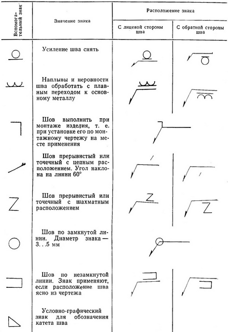
The weld symbol is divided into the following parts:
1. Auxiliary signs of a seam along a closed line and an assembly seam (placed at the junction of the leader with the shelf).
2. Designation of the weld in accordance with the relevant standard for types and structural elements of welded joints.
3. Alphanumeric designation of the weld seam in accordance with the relevant standard (separated from the previous part of the designation by a hyphen).
4. Designation of the welding method in accordance with the same standard (may not be indicated).
5. Sign and size of the leg of the seam (separated from the previous part by a hyphen).
6. The sign of an intermittent or spot seam and the length of the section to be welded or the step size according to the relevant standards (separated from the previous part by a hyphen).
7. Auxiliary signs.
All seams of the same type with the same cross-sectional dimensions, having the same symbol, are assigned the same number, which is affixed on the extension line of one of the seams along with the designation, and on all other seams - only their number. If all the seams in the drawing are the same and are depicted on one side (front or back), then the seams are not assigned a serial number and are designated only by leader lines without shelves, except for the seam on which the symbol is indicated. If all the seams in one drawing are made according to the same standard, then the standard number in the seam image may not be indicated, but only indicated in the technical requirements or in the seam table.
The consumables are indicated on the drawing in the technical requirements or in the seam table.
Examples of images of welds are shown in table. 2.5.
This article provides some information on the design of working drawings of elements of metal structures that are permissible for and KM. Let's consider these recommendations.
Formats and title blocks
The dimensions of the formats of the drawing sheets used in the execution of the KM and KMD drawings must comply with GOST 2.301-68 ESKD. Formats.Forms, sizes and the procedure for filling in the main inscriptions and additional columns to them, as well as the dimensions of the frames in the drawings and in text documents must comply with GOST 21.101-97 SPDS (DSTU B A.2.4-4: 2009 SPDB) in form 3, 4, 5 and 6. For working drawings of shipping marks of structural elements, a title block in form 4 is used. Such a title block is shown in the following figure.
Drawing lines
The name, outline, thickness and main purpose of the lines that are used in the execution of drawings of KM and KMD must comply with GOST 2.303-68 ESKD. Lines.Fonts
The inscriptions on the drawings must comply with GOST 2.304-81 ESKD. Drawing fonts. Recommended font sizes.- 2.5; 3.5 - for text instructions and explanatory inscriptions when depicting elements and details;
- 3.5; 5 - for image titles, headings in text instructions and statements;
- 5 - for designations of brands in statements and specifications;
- 7; 10 - for writing sheet numbers and marks above the design image.
The scale
The scale of images and their designation must comply with GOST 2.302-68 ESKD. The scale. The choice of scales should be made taking into account the complexity of the images and use the smallest possible scale, ensuring the clarity of the drawing and copies from it.Recommended scales for KM drawings:
- general view, plans, sections - 1:50, 1: 100, 1: 200, 1: 400;
- general schematic drawings - 1: 400, 1: 500;
- layout of elements - 1: 100, 1: 200, 1: 400;
- cross sections and views - 1:50, 1:75, 1: 100, 1: 200;
- structural elements - 1:15, 1:20, 1:50, 1: 100;
- knots - 1:10, 1:15, 1:20, 1:25.
Recommended scales for structural steel drawings:
- assembly plans, diagrams - 1: 100, 1: 200, 1: 400;
- sections of solid-wall and lattice structural elements - 1:10, 1:15, 1:20, 1:25.
Geometric diagrams of spatial lattice metal structures are depicted in one scale for all three dimensions (length, height, width). Long solid-wall structures:, beams, columns are depicted without observing the scale in length, while maintaining the relative position of parts and holes. Lattice structures (trusses, ties, etc.) are usually depicted in two scales, they reduce the diagram of the axes of the elements more than their transverse dimensions and while maintaining the same image scale within the nodes and small parts (gussets, gaskets, etc.). NS.). For metal structures of the same type shown on one sheet, the same scale should be used.
The scale does not have to be indicated on the drawings. The exception is structural design drawings, in this case the scale is indicated in the title block.
Images
Views (facades), plans, sections, sections, external elements (nodes, fragments) are depicted in accordance with GOST 2.305-68 ESKD "Images - views, sections, sections" and taking into account additional requirements in accordance with GOST 21.101-97 SPDS (DSTU B A. 2.4-4: 2009 SPDB) and GOST 21.501-93 SPDS (DSTU B A.2.4-7: 2009 SPDB).When performing working detail drawings of shipping marks, drawings of parts and assemblies of individual structural elements - trusses, columns, beams, as well as joints of structural elements to each other, the arrangement of views is adopted in accordance with GOST 2.410-68 ESKD. Rules for the execution of drawings of metal structures. This arrangement of views is shown in the following figure.
 The top view is located in the projection link above the main view,
bottom view - under the main view,
right view - to the right of the main view,
left view - to the left of the main view.
Above each species, except for the main one, an inscription is made according to the type "A", and the direction of sight is indicated by an arrow, indicated by the corresponding letter.
Sending elements must be depicted so that the main projection (main view) corresponds to the working position and gives the most complete picture of their shapes and sizes, namely: horizontal elements - in a horizontal position, vertical - in a vertical position, inclined - in an inclined position.
When depicting steel structures, they show with solid lines all visible parts located on the face closest in the direction of view, and invisible ones - only those that are located close to the visible ones. Visible parts located deep behind the front edge, and invisible, separated from the visible by an air gap, are not shown in the drawing.
When making cuts and sections, elements falling into the cutting plane are not hatched.
Dimensioning rules
Dimensioning on drawings is carried out in accordance with GOST 2.307-68 ESKD "Application of dimensions and maximum deviations", taking into account additional requirements.The total number of dimensions in the drawing should be minimal, but sufficient for the manufacture and control of both individual parts and the structural element as a whole. The number of dimensions and their location on the drawing should provide ease of reading the drawing and linking with other elements.
All dimensions in the drawings of metal structures are in millimeters.
Dimension lines must be parallel to the line you are specifying. The distance between parallel dimension lines should be 7-10 mm, and the distance from the dimension line to the contour lines parallel to them should be about 15 mm when the dimension line is below or to the right of the contour line, and 7-10 mm when the dimension line is above or to the left of the contour line. At the intersection of the dimension and extension lines or with a contour line, serifs are placed in the form of thin solid lines 1-3 mm long, held with an inclination to the right at an angle of 45 ° to the dimension line, while the dimension lines should protrude 1-3 mm beyond the extreme extension lines.
When dimensioning the diameter or radius of a circle or arc, as well as an angular dimension, the dimension line is constrained by arrows.
The diameters of the holes prevailing in the drawing and the cuts of the parts are stipulated in the technical requirements and are not affixed to the drawing.
When dimensioning the height or width of the section of rolled profiles (angles, I-beams, channels), the dimensional chain is not closed. In this case, the dimensions are attached to the plane or face, the elevation or binding of which must be observed in the structure. The risks of rolling and bent corners are tied to the butt.
In welded beams, the full height of the support part is indicated, that is, the size that must be strictly maintained. Such dimensions are framed and indicate the size of the tolerance. The thickness of the shelves and the height of the wall are also indicated, but the size between the lower surface of the lower chord and the bottom of the supporting rib is not indicated, due to which inaccuracies during assembly are compensated.
![]() When displaying an unequal corner, it is necessary to indicate its position by putting down the width of one of the shelves.
When displaying an unequal corner, it is necessary to indicate its position by putting down the width of one of the shelves.
The bevels in the drawing are indicated by linear dimensions.


Details in the drawings are indicated by numbers placed in circles, the diameter of the circle is 8-10 mm. The circle for the designation of parts is connected to the image of a thin part wavy line with an arrow at the path or a point at the end within the path.
Mutually mirror parts are designated by the index "T" (sic) and "H" (vice versa). In this case, the "T" index is written near the number at the top right, and the "H" index is written at the bottom right.

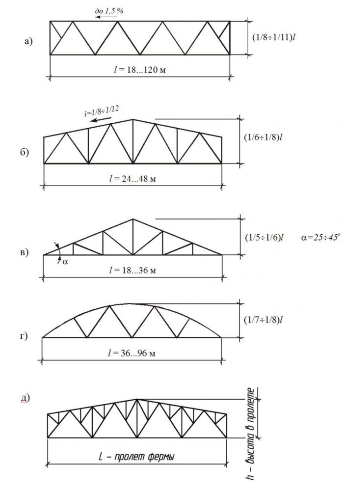
Classification of trusses: a - with parallel belts, b - polygonal,
c - triangular, d - segmental, d - truss.
Compared to solid beams, trusses are economical in terms of metal consumption, they are easily given any shape required by the conditions of technology, work under load or architecture, they are relatively easy to manufacture, they are used under a wide variety of loads; Depending on the purpose, they are given a wide variety of structural forms - from light bar structures to heavy trusses, the rods of which can be assembled from several elements of large profiles or sheets.
Light trusses, as a rule, are single-plane, the rods of which are made up of rolled or bent sections; heavy trusses, as a rule, are two-plane - their rods are made up of heavy sheet or rolled profiles.
The most rational form of cross-section of elements of light trusses is a tubular section, trusses made of pipes are economical in weight, they resist corrosion well, but some complication of nodes and a shortage of pipes limit their use.
The nodes of various trusses can have a variety of designs depending on the design task and the conditions for its design. Examples of the design and design of drawings of some nodes of typical roof trusses for covering industrial buildings are shown in the following figure.

Beams
Beams are structural elements of a solid section that work in bending, the length of the beams significantly exceeds the dimensions of the section. Due to their simplicity and low manufacturing cost, convenient structural form, and low construction height, beams are widely used in building structures. Beams are used as load-bearing elements in the roofs and floors of buildings and structures, work sites, flyovers, galleries, bridges, and the like. Beams up to 15 ... 20 m long are rational, but in bridges the spans of beams can reach several hundred meters.
The section between the supports is called the span of the beam, depending on the number of supports, the beams are called single-span and multi-span, if the section of the beam extends beyond the support, then it is called a cantilever, and the beam is cantilever.
By the type of section, beams can be rolled or composite. Metal beams are most often designed with an I-section. This is due to the convenience of making wiring connections. Lightweight beams are often made from channels (rolled or bent).
Depending on the span and the load, the beams are made from profiled steel, or a composite section from sheet steel. The use of beams of composite section is advisable when it is not possible to use rolled or bent sections due to the limited range of products.

Among composite beams, welded beams are more economical than riveted or bolted beams. They consist of shelves (belts) and walls (which are made of sheet steel), connected to each other in a single section. The most common is the symmetrical I-beam formed from three sheets by welding. Such beams are used if it is impossible to use rolled beams due to the large span and load.
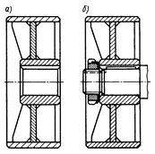
A beam cage is a system that consists of one type, or several types of cross beams. There are three types of beam connection possible in a beam cage system:

storey - secondary beams are installed on the upper belt below the placed structures. Such a connection is convenient during installation, but it requires a greater constructive floor height;
at one level - the floor beams are attached to the main one from the side through the stiffeners so that the upper flanges of the main beam and the floor beams are at the same level;
lowered - the auxiliary beams are attached to the main beam from the side so that the upper flanges of the main beam and the deck beams are on the same level, and the upper flanges of the auxiliary beams are located below the upper flanges of the main beam. Such a constructive solution is often used in complex type beam cages to reduce the building (constructive) floor height h p ..
Columns are vertically arranged bar elements, along which the load from the overlying structures is transferred to the foundations. They distinguish between: the upper part - the head on which the overlying structures rest; bar - the main part of the column, transferring the load from top to bottom, and the base (shoe) - the lower part of the column, transferring the load from the bar to the foundation.  If the column works on the perception of the load from one longitudinal force applied along the center of gravity of the section, then it is called centrally compressed. If the longitudinal force does not coincide with the center of gravity of the section or any transverse loads are applied to the bar, then, in addition to compression, bending occurs, and the column is called eccentrically compressed.
The cross-section of the column bar can be solid or through (lattice), consisting of separate branches connected by braces or strips.
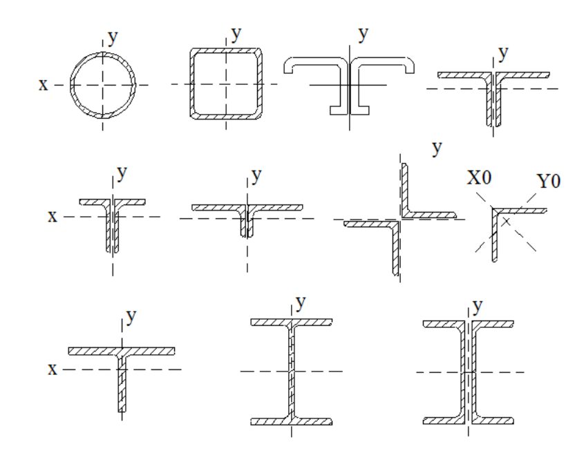
Consider the design features of the centrally compressed columns. Solid and through columns with a constant cross-section bar are most common in central compression. Solid columns are used at high loads and low heights, through, on the contrary - at lower loads and high heights.
Sections of solid columns are of two types: open type - most often in the form of a wide-flange I-beam (rolled or welded), as well as a cross-section made of rolled profiles or sheets; closed type in the form of round and square pipes welded by automatic welding from sheet or rolled profiles. The following figure shows the section types of solid columns.
The connection of the branches at through columns is carried out using strips and using braces (lattice). The connection of the branches of the column with braces gives the bar greater rigidity; therefore, such columns are used under significant loads. 


General view of slats and lattice of through columns
- Composition based on Plastov's painting “In the Summer
- Pavel Fedotov. Fresh cavalier. The eternal consequences of the revelry. Pavel Fedotov's "Fresh Cavalier" is not outdated and today the Cavalier has missed his chance
- Freedom leading the people to the barricade
- "Hero of Our Time", Pechorin: characteristics